
Image-based virtual sensor scheme

A technology of virtual sensor and camera sensor, applied in the field of image processing, can solve the problems of service robot movement control adjustment, unable to image analysis and so on

Pending Publication Date: 2021-11-30
浙江大学湖州研究院 +1
View PDF1 Cites 0 Cited by
  • Summary
  • Abstract
  • Description
  • Claims
  • Application Information

AI Technical Summary

Problems solved by technology

Correspondingly, a failed software update of a drone may require maintenance by a technician, while a failed update of a virtual machine in the cloud hosting a virtualized control service may only require restoring a backup of the virtual machine, but does not solve the problem of existing image sensor failures. It can realize the control and adjustment of the movement of the service robot or the vehicle, but it cannot analyze the images taken by the service robot or the vehicle to obtain the proportion of the movement offset, etc. For this reason, we propose a Image-based virtual sensor scheme

Method used


Image

  • Image-based virtual sensor scheme
  • Image-based virtual sensor scheme
  • Image-based virtual sensor scheme

Examples


Embodiment 1

[0017] see Figure 1-Figure 3 , the present invention provides a technical solution: an image-based virtual sensor solution, the steps of system operation include the following steps;

[0018] S1. Shooting the traveling route through the camera sensor: the traveling route is photographed through the camera sensor, and the captured image is transmitted to the image collection module, and the image collection module pre-processes the image;

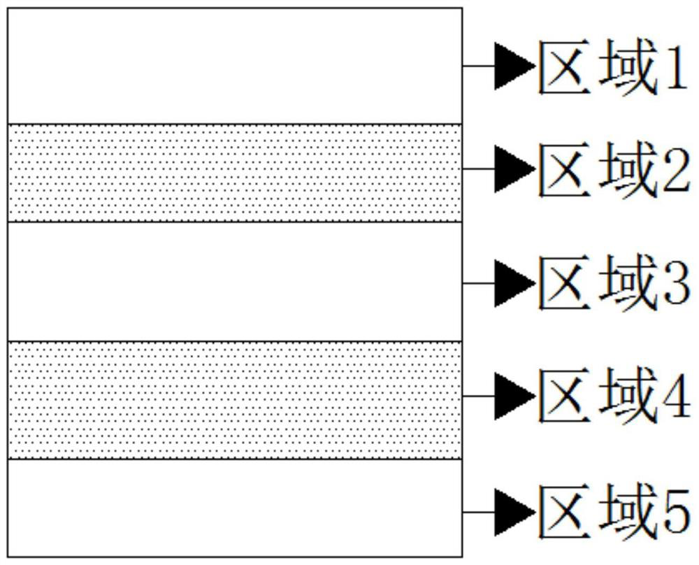
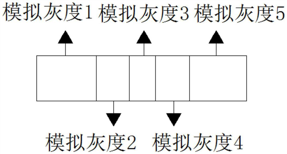
[0019] S2. The image collection module transmits the image to the information processing module: when the information processing module receives the image, it divides the collected image into 5 areas, including area 1, area 2, area 3, area 4 and area 5 , area 1, area 3, and area 5 are used for color block recognition, area 2 and area 4 are used for grayscale line inspection, and the grayscale line inspection method is to divide area 2 and area 4 into 5 areas, each of which Correct the body of the car by calculating the proportion of the tr...

Embodiment 2

[0022] see Figure 1-Figure 3 , the difference from Embodiment 1 is that this image-based virtual sensor solution also includes the following: including a control chip, an image collection module and a camera sensor, the control chip is electrically connected with a signal processing module, a communication module, a power module, positioning module and auxiliary module;

[0023] The camera sensor is electrically connected to the image collection module, the image collection module is electrically connected to the signal processing module, the signal processing module is electrically connected to the control chip, and the camera sensor is used to photograph the driving of the vehicle The image of the path, the image collection module is used to receive the picture taken by the camera sensor, the signal processing module is used to process the image transmitted by the image collection module, and the signal processing module transmits the processing information to the The cont...


PUM


Abstract

The invention discloses an image-based virtual sensor scheme. The method for system operation includes: S1, the camera sensor shoots the advancing route: the camera sensor shoots the advancing route, and transmits a shot image to an image collection module, where the image collection module is used for pre-processing the image; s2, the image collection module transmits the image to an information processing module, when the information processing module receives the image, the collected image is divided into five areas including an area 1, an area 2, an area 3, an area 4 and an area 5, wherein the area 1, the area 3 and the area 5 are used for color block identification, and the area 2 and the area 4 are used for gray level line patrol. According to the invention, the proportion of the service robot or the vehicle in the image segmentation area is obtained through image analysis, so that the service robot or the vehicle is moved and adjusted, and a normal moving track is completed.

Description

technical field [0001] The invention belongs to the technical field of image processing, and in particular relates to an image-based virtual sensor scheme. Background technique [0002] Image processing, the technique of analyzing an image with a computer to achieve a desired result. Also known as image processing. Image processing generally refers to digital image processing. A digital image refers to a large two-dimensional array obtained by shooting with industrial cameras, video cameras, scanners and other equipment. The elements of this array are called pixels, and their values ​​are called grayscale values. Image processing technology generally includes three parts: image compression, enhancement and restoration, matching, description and recognition. With the intelligent development of science and technology, more and more products carry various sensors for automatic recognition, and Vehicles and service robots are equipped with various sensors. Among the sensors, ...

Claims


Application Information

Patent Timeline
IPC IPC(8): G06T7/11G06N3/04G06N3/08
Inventor 庞作伟黎明和
Owner 浙江大学湖州研究院
Features
  • Generate Ideas
  • Intellectual Property
  • Life Sciences
  • Materials
  • Tech Scout
  • Unparalleled Data Quality
  • Higher Quality Content
  • 60% Fewer Hallucinations
Learn More