Bronchoscope cleaning and disinfecting machine
A technology for cleaning and disinfecting bronchoscopes, applied in the field of bronchoscopes, can solve the problems of slipping, increasing the labor of medical staff, inconvenient clamping and fixing of bronchoscopes, etc., and achieves the effects of improving intelligence, enhancing stability, and ensuring cleanliness
- Summary
- Abstract
- Description
- Claims
- Application Information
AI Technical Summary
Problems solved by technology
Method used
Image

Examples
Embodiment 1
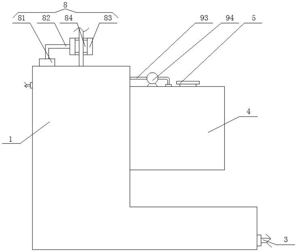
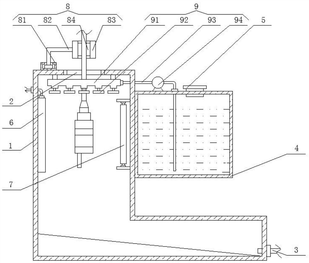
[0033] Such as Figure 1-Figure 4 As shown, the present invention provides a bronchoscope cleaning and disinfection machine, which includes a cabinet 1 , a fixing mechanism 8 and a cleaning mechanism 9 .
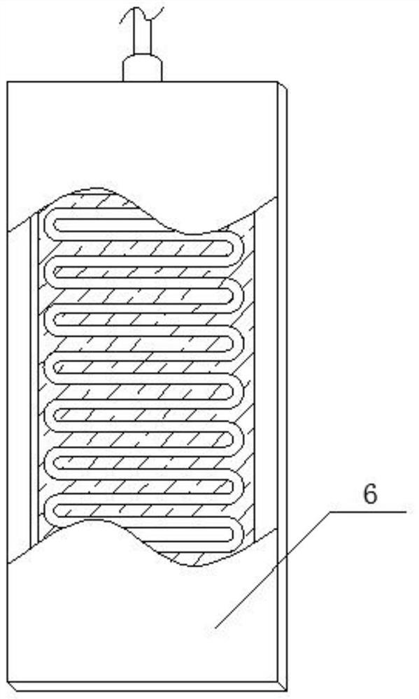
[0034] The top of the cabinet 1 is provided with a feed port 2, which is convenient for extending the bronchoscope into the inside of the cabinet 1, and the bottom of one side of the cabinet 1 is fixedly connected with a drain pipe 3, which is convenient for discharging the waste water generated during the cleaning and disinfection of the bronchoscope , one side of the cabinet 1 is fixedly connected with a water tank 4, the top thread of the water tank 4 is sleeved with a water inlet plug 5, the inside of the cabinet 1 is provided with a bronchoscope, and one side of the inner cavity of the cabinet 1 is fixedly installed with a heating plate 6, the heating plate The inside of 6 is fixedly equipped with a resistance wire, and the heating plate 6 is located on one side of the ...
Embodiment 2
[0038] Such as Figure 5 and Figure 6As shown, in this embodiment, a water level monitoring mechanism 10 is added on the basis of Embodiment 1. The water level monitoring mechanism 10 includes a liquid level sensing probe 101, a controller 102 and a warning light 103. The liquid level sensing probe 101 is fixedly installed in the water tank 4 At the bottom of the inner side, the warning light 103 is fixedly installed on one side of the top of the water tank 4, and the controller 102 is fixedly installed on the side of the water tank 4. The input end of the controller 102 is connected to the output end signal of the liquid level sensing probe 101, and the controller 102 The output terminal of the signal receiving module 102a is electrically connected to the input terminal of the warning light 103, and the controller 102 includes a signal receiving module 102a, a signal processing module 102b and a circuit control module 102c, and the input terminal of the signal receiving modu...
Embodiment 3
[0040] Such as Figure 7 As shown, the present embodiment adds an energy recovery mechanism on the basis of the second embodiment. The energy recovery mechanism includes a rotating shaft 11, and the outside of the rotating shaft 11 is fixedly connected with a plectrum 12. Inside, the plectrum 12 is located below the nozzle 92, and the plectrum 12 and the rotating shaft 11 are perpendicular to each other. One end of the rotating shaft 11 is fixedly connected to a generator 13, and the outer part of the generator 13 is fixedly sleeved with a protective box 14 to generate electricity. One side of the machine 13 is provided with a power storage structure 15, the power storage structure 15 includes a protective cover 151, the protective cover 151 is fixedly connected to the top of the chassis 1, and the inside of the protective cover 151 is fixedly connected with a battery 152, and one side of the battery 152 passes through The transmission line 153 is electrically connected to one...
PUM
 Abstract
Description
Claims
Application Information