Internal cleaning device for hydraulic valve block machining and cleaning method thereof
What is Al technical title?
Al technical title is built by PatSnap Al team. It summarizes the technical point description of the patent document.
A technology for cleaning devices and hydraulic valves, which is applied in the direction of cleaning methods using liquids, cleaning methods and utensils, chemical instruments and methods, etc., and can solve problems such as imperfect device structures
Inactive Publication Date: 2021-12-03
湖南兴众科技有限公司
View PDF7 Cites 0 Cited by
Summary
Abstract
Description
Claims
Application Information
AI Technical Summary
This helps you quickly interpret patents by identifying the three key elements:
Problems solved by technology
Method used
Benefits of technology
Problems solved by technology
[0003] The object of the present invention is to provide an internal cleaning device for hydraulic valve block processing and its cleaning method, so as to solve the problem of imperfect structure of the existing device in the above-mentioned background technology
Method used
Image
Click on the blue label to locate the original text in one second.
Reading with bidirectional positioning of images and text.
Examples
Embodiment Construction
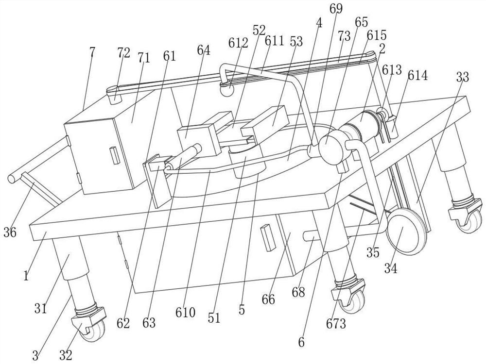
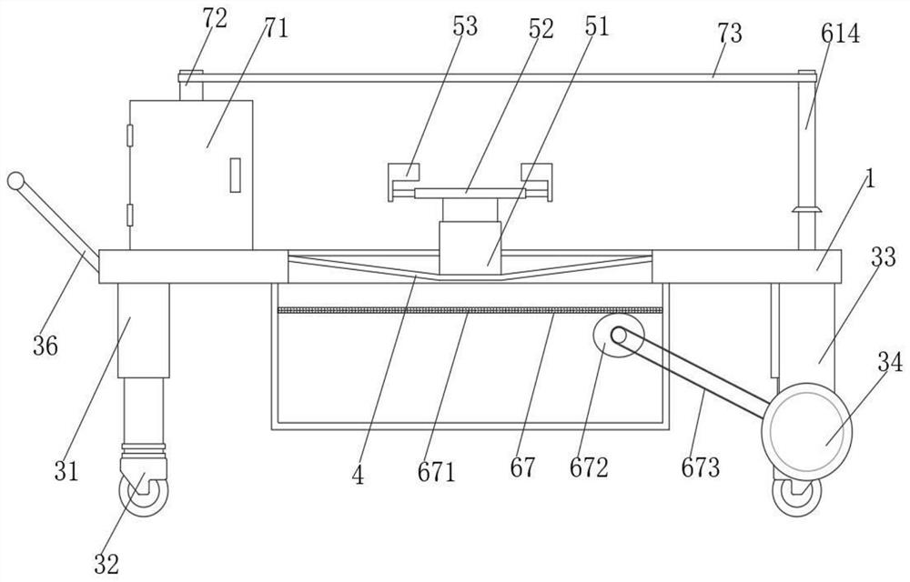
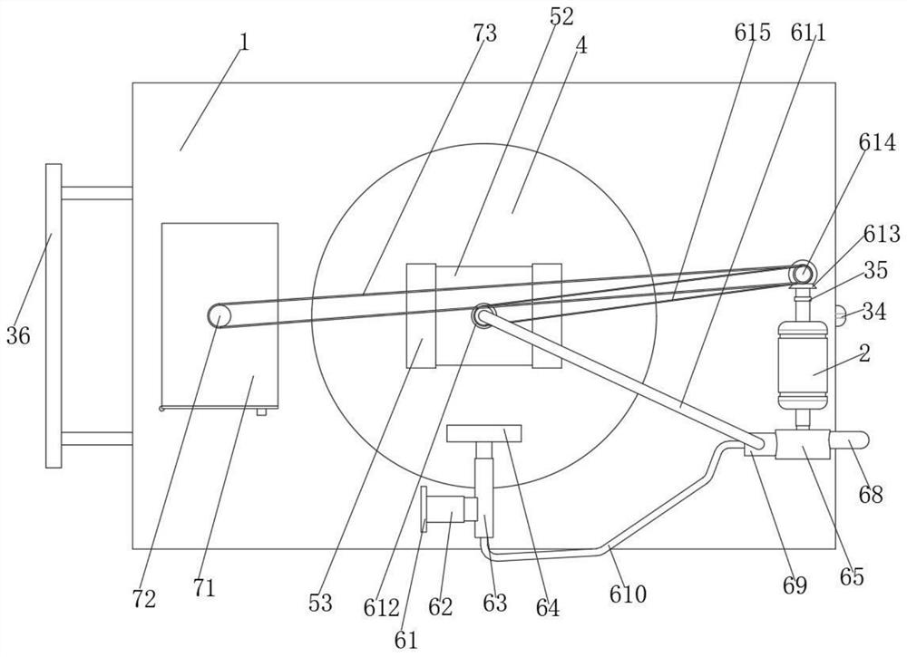
[0025] The present invention provides such Figure 1-5 The shown internal cleaning device for processing a hydraulic valve block and its cleaning method includes a round through groove plate 1, and the middle part on the right side of the top of the round through groove plate 1 is fixedly connected with a double-axis motor 2 through a connecting block, and the double-axis motor 2 provides Power support, the bottom of the round channel plate 1 is equipped with a moving mechanism 3, the inner side of the round channel plate 1 is fixedly connected with a bucket-shaped filter body 4, the middle part of the top of the bucket-shaped filter body 4 is fixedly connected with a fixing mechanism 5, and the round channel plate A cleaning mechanism 6 is installed on the front of the top, and a drying mechanism 7 is installed on the left side of the round slot plate 1 top.
[0026] The moving mechanism 3 includes telescopic struts 31, four telescopic struts 31 are respectively fixedly conne...
PUM
Abstract
The invention discloses an internal cleaning device for hydraulic valve block machining and a cleaning method thereof, and relates to the technical field of hydraulic valve block cleaning. The internal cleaning device comprises a circular through groove plate, and a double-shaft motor is fixedly connected with the middle of the right side of the top of the circular through groove plate through a connecting block. According to the internal cleaning device for hydraulic valve block machining and the cleaning method thereof, the double-shaft motor provides power support, a bucket-shaped filter screen body, a stabilizing plate, a telescopic transverse body, a telescopic water pipe, a hollow through net body, a water pump, a water tank box, a slag separation structure, a slag separation net plate, an eccentric wheel rod, a lower conveying belt, a water pumping bent pipe, a water drainage main pipe, a hose, a bent water pipe, a water spraying body, a bevel gear, a bevel gear rod and a conveying connecting belt are used, so that the hydraulic valve block is conveniently and comprehensively cleaned; and meanwhile, residues are removed in time, a telescopic adjusting seat, a bidirectional telescopic plate and a clamping block body are used for conveniently fixing the hydraulic valve block, and a drying box, a fan body, an upper conveying belt, a heating plate and a bearing net plate are used for conveniently drying the cleaned hydraulic valve block.
Description
technical field [0001] The invention relates to the technical field of hydraulic valve block cleaning, in particular to an internal cleaning device for hydraulic valve block processing and a cleaning method thereof. Background technique [0002] The hydraulic valve block is a hydraulic component mounting seat. The hydraulic component is connected to the oil hole of the hydraulic valve block through fasteners. The oil hole is drilled in the vertical and horizontal channels inside the valve block according to the passage requirements of the hydraulic system schematic diagram. The hydraulic valve The block can be used to control the on-off of the oil, gas, and water pipeline systems of the hydropower station. For the hydraulic valve block, after the processing of the hydraulic valve block, the hydraulic valve block usually needs to be cleaned to remove the residue on the hydraulic valve block. However, due to the multi-channel oil hole passages inside the hydraulic valve block,...
Claims
Application Information
Patent Timeline
Application Date:The date an application was filed.
Publication Date:The date a patent or application was officially published.
First Publication Date:The earliest publication date of a patent with the same application number.
Issue Date:Publication date of the patent grant document.
PCT Entry Date:The Entry date of PCT National Phase.
Estimated Expiry Date:The statutory expiry date of a patent right according to the Patent Law, and it is the longest term of protection that the patent right can achieve without the termination of the patent right due to other reasons(Term extension factor has been taken into account ).
Invalid Date:Actual expiry date is based on effective date or publication date of legal transaction data of invalid patent.