
Round tube laser cutting machine convenient to feed

A technology of laser cutting machine and round pipe, applied in laser welding equipment, welding equipment, metal processing equipment, etc., can solve problems such as jamming, cumbersome replacement of lifting plates, and uneven end faces of round pipes, so as to increase the cutting efficiency , Convenient and orderly placement, easy to unload the effect

Active Publication Date: 2021-12-03
浙江沪云光电设备股份有限公司
View PDF8 Cites 2 Cited by
  • Summary
  • Abstract
  • Description
  • Claims
  • Application Information

AI Technical Summary

Problems solved by technology

[0003]At present, in order to realize automatic feeding and continuous feeding, the laser cutting machine will be equipped with feeding components when laser cutting the long round tube, but the current laser cutting machine The feeding assembly is generally fixed, and can only place a fixed number of round tubes. It is troublesome to add round tubes according to different production conditions, and the placed round tubes will also affect the upright position of the round tubes due to their uneven end faces. When the round tube is lifted and loaded, the jacking block is fixed, which is inconvenient to jack up round tubes with different external diameters. It is cumbersome to replace the jacking plate, which affects the processing efficiency. When unloading, if there are sundries on the rack or the round tube, it may affect the automatic unloading efficiency of the round tube, resulting in jamming

Method used


Image

  • Round tube laser cutting machine convenient to feed
  • Round tube laser cutting machine convenient to feed
  • Round tube laser cutting machine convenient to feed

Examples


Embodiment Construction

[0033] In order to make the technical means, creative features, goals and effects achieved by the present invention easy to understand, the present invention will be further described below in conjunction with specific embodiments.

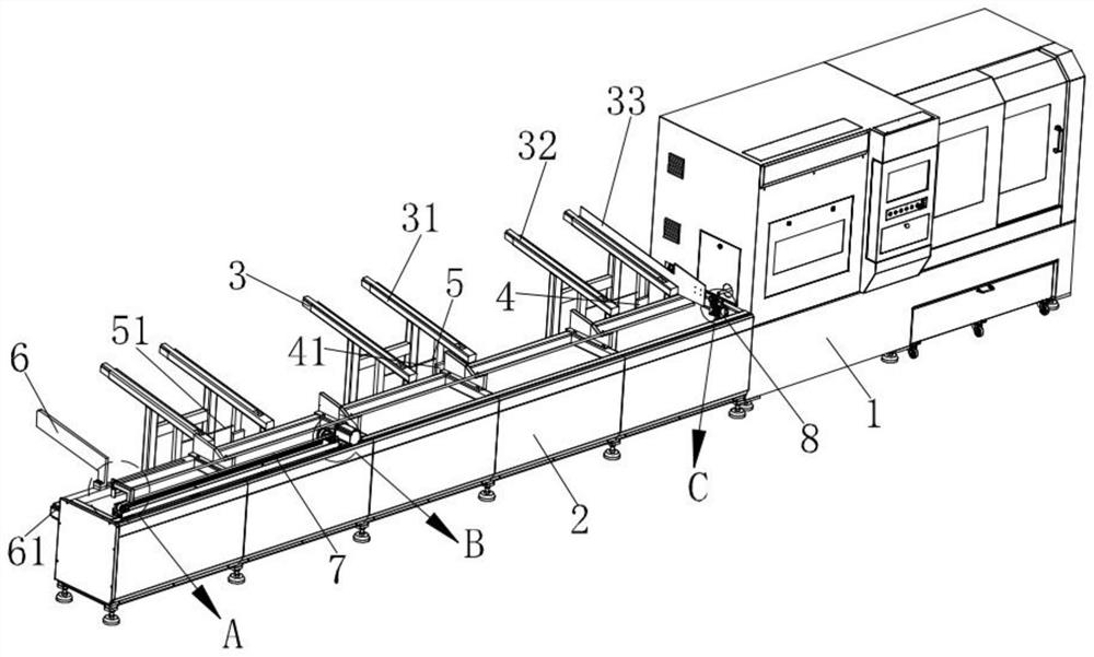
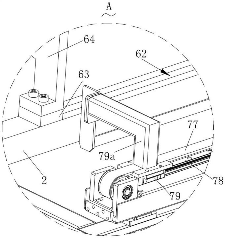
[0034] Such as Figure 1-Figure 10 As shown, a circular tube laser cutting machine for convenient feeding according to the present invention includes a body 1, a fixing frame 2 is installed at one end of the body 1, and a discharging structure is installed at one end of the fixing frame 2 3. A jacking structure 4 is installed at one end of the fixing frame 2, a vibrating structure 5 is arranged at one end of the lifting structure 4, an alignment structure 6 is installed at the top of the fixing frame 2, and an alignment structure 6 is installed at the top of the fixing frame 2. 2 is provided with a feeding structure 7, and an adjustment structure 8 is installed on the fixed frame 2;

[0035] The discharge structure 3 includes a discharge rack 31,...


PUM


Abstract

The invention relates to the technical field of laser cutting, in particular to a round tube laser cutting machine convenient to feed. The machine comprises a machine body, a fixing frame is mounted at one end of the machine body, a discharging structure is mounted at one end of the fixing frame, a jacking structure is mounted at one end of the fixing frame, a vibration structure is arranged at one end of the jacking structure, an aligning structure is installed at the top end of the fixing frame, a feeding structure is arranged on the fixing frame, and an adjusting structure is installed on the fixing frame. By arranging the discharging structure on one side of the fixing frame, to-be-cut round steel pipes can be placed in sequence so as to facilitate continuous feeding, the number of the round pipes needing to be placed can be adjusted according to actual needs so as to facilitate better feeding, the arrangement of the aligning structure is matched, so that the cutting efficiency is improved, and the end faces of the placed round pipes can be extruded and aligned, so that the feeding work of the round pipes can be better carried out.

Description

technical field [0001] The invention relates to the technical field of laser cutting, in particular to a circular tube laser cutting machine for convenient feeding. Background technique [0002] The laser cutting machine focuses the laser light emitted from the laser device into a high power density laser beam through the optical path system. The laser beam irradiates the surface of the workpiece to make the workpiece reach the melting point or boiling point, and at the same time, the high-pressure gas coaxial with the beam blows away the molten or vaporized metal. At present, when the long round tube is cut into multiple short round tubes of specific sizes according to the needs, in order to ensure that the cutting surface of the round tube is flat, a laser cutting machine is also used for operation. [0003] At present, in the laser cutting of long round tubes, in order to realize automatic feeding and continuous feeding, the laser cutting machine will be equipped with fe...

Claims


Application Information

Patent Timeline
Patent Type & Authority Applications(China)
IPC IPC(8): B23K26/38B23K26/70
CPCB23K26/38B23K26/702Y02P70/10
Inventor 王世伟刘小岗
Owner 浙江沪云光电设备股份有限公司
Learn More