
Efficient supercharged cotton yarn environment-friendly dyeing device

A technology of dyeing device and yarn dyeing machine, which is applied in the direction of cleaning device for processing textile materials, liquid/gas/steam processing transmission device, liquid/gas/steam yarn/filament processing, etc., and can solve the problem of contact between yarn and dyeing agent Insufficient, affecting the dye liquor filtration effect, surface wool clogging and other problems, to achieve the effect of facilitating loading and unloading work, improving loading and unloading speed, and increasing contact time

Inactive Publication Date: 2022-07-15
李爱茹
View PDF0 Cites 1 Cited by
  • Summary
  • Abstract
  • Description
  • Claims
  • Application Information

AI Technical Summary

Problems solved by technology

[0004] (1) The dyeing method of the existing skein dyeing machine usually adopts the method of spraying the dyeing agent for dyeing. In this way, the contact between the yarn and the dyeing agent needs to reach a certain period of time before a good dyeing effect can be guaranteed. , the dyeing time is too long, the production efficiency is low, and the working time is too short, it is easy to cause insufficient contact between the yarn and the dyeing agent, and the dyeing effect is not good;
[0005] (2) In the work of dye liquor circulation, it is usually necessary to remove impurities from the dye liquor before putting it into use again. However, in this process, the surface of the filter screen is easily blocked by a large amount of wool after long-term use , which in turn affects the filtering effect of the dye liquor. At the same time, the work of manually repairing the filter screen is too complicated and time-consuming

Method used


Image

  • Efficient supercharged cotton yarn environment-friendly dyeing device
  • Efficient supercharged cotton yarn environment-friendly dyeing device
  • Efficient supercharged cotton yarn environment-friendly dyeing device

Examples


Embodiment 1

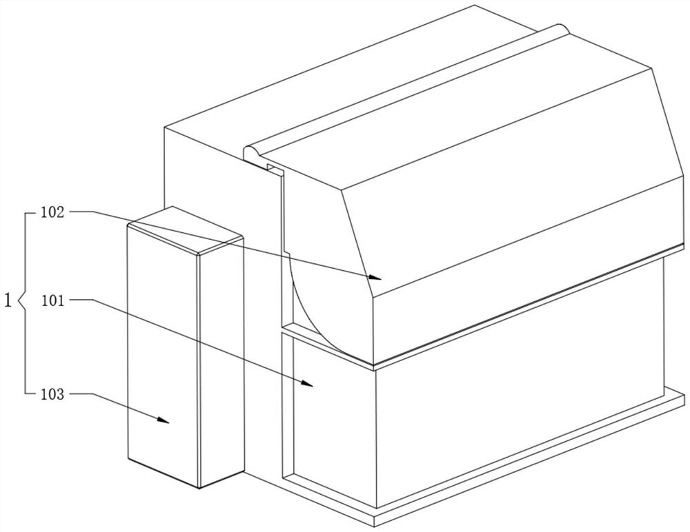
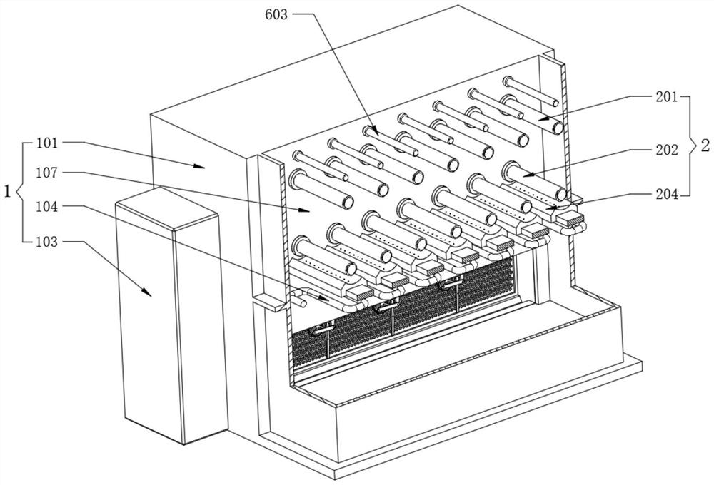
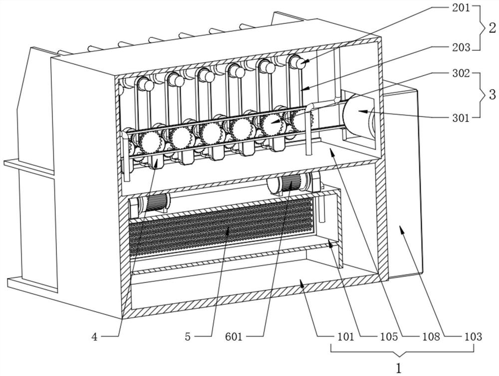
[0043] see Figure 1-5 , a high-efficiency pressurized cotton yarn environmentally friendly dyeing device, including a yarn dyeing machine 1 and a winding and dyeing component 2:

[0044] see figure 1 , figure 2 and image 3, the yarn dyeing machine 1 also includes a body 101, the surface of the body 101 is rotatably installed with an organic cover 102, a dyeing chamber 107 is fixed on one side of the body 101, and the interior of the dyeing chamber 107 provides a place to complete the yarn dyeing, and the other side of the body 101 A transmission chamber 108 is fixedly opened, and a coil heater 104 is fixedly installed under the inside of the body 101. After the coil heater 104 is energized, it can heat the dyeing agent, thereby improving the dyeing effect. The inner bottom end of the body 101 is fixedly provided with a circulating liquid tank 105. A filter screen 5 is fixedly assembled on the inner side of the circulating liquid tank 105, and the dye enters the inside of...

Embodiment 2

[0049] see Figure 5-6 , a high-efficiency pressurized cotton yarn environmentally friendly dyeing device, including a hydraulic pressurizer 4:

[0050] see Image 6 , the water pressure press 4 also includes a water pressure shell 401. The pressure water shell 401 is installed in the transmission chamber 108 at equal distances. One end of the lower winding roller 202 is fixedly sleeved with a driving gear 206, and the transmission chamber 108 rotates inside. A driven gear 207 is installed, and the driving gear 206 is meshed with the driven gear 207. When the lower winding roller 202 rotates, the driving gear 206 will drive the driven gear 207 to rotate together, and a crankshaft 404 is installed on the inner top of the pressurized water shell 401. One end of the crankshaft 404 and one end of the driven gear 207 are fixedly sleeved with a secondary belt 208. After the transmission of the secondary belt 208, the crankshaft 404 can be rotated inside the pressurized water shell ...

Embodiment 3

[0053] see Figure 7 , a high-efficiency pressurized cotton yarn environmentally friendly dyeing device, including winding and dyeing components 2:

[0054] see Figure 7 , the side walls of the upper winding roller 201 and the lower winding roller 202 are fixedly welded with an inner rod 209, and the outer surface of the inner rod 209 is movably sleeved with an outer tube 210. The tube 210 is pulled out. After the yarns are wound on the surfaces of the two outer tubes 210, the outer tube 210 is reassembled. The inner wall of the outer tube 210 is fixedly provided with a convex strip 211, and the surface of the inner rod 209 is fixed with a groove 212, and the convex strip 211 is movable. embedded in the groove 212 .

[0055] In use: in the process of yarn feeding, first pull out the outer tube 210 at one end of the upper winding roller 201 and the lower winding roller 202, wrap the yarn on the surfaces of the two outer tubes 210, and reassemble the outer tube 210. During t...


PUM


Abstract

The invention discloses an efficient supercharged cotton yarn environment-friendly dyeing device, and belongs to the field of yarn processing equipment, the efficient supercharged cotton yarn environment-friendly dyeing device comprises a yarn dyeing machine, a yarn coiling and dyeing assembly, a water pressure pressurizer and a filter screen wall scraping assembly, one end of the upper winding roller and one end of the lower winding roller are fixedly sleeved with a first-stage belt, liquid spraying holes are formed in the surface of the winding base at equal intervals, a water outlet pipe and a water suction pipe are fixedly connected to the bottom end of the water pressing shell, and the water outlet pipe leads to the interior of the winding base and communicates with the liquid spraying holes; the secondary motor is fixedly installed at one end of the upper surface of the circulating liquid box, a traditional dyeing mode of spraying dye liquor is changed, the dyeing time is shortened, meanwhile, the dyeing effect is guaranteed through a mode of mechanically increasing water pressure, additional electric supercharging equipment is not needed, in addition, charging and discharging are convenient, and the cost is reduced. And manual cleaning of the filter screen can be replaced.

Description

technical field [0001] The invention relates to the field of yarn processing equipment, and more particularly, to a high-efficiency pressurized type environmental protection dyeing device for cotton yarn. Background technique [0002] Yarn dyeing, a dyeing process for yarn. Mainly include: "beam dyeing", "hank dyeing", "cheese dyeing", "compressed cheese dyeing" and "filling dyeing", etc. The above are uniform dyeing processes, and "spaced dyeing" is also yarn dyeing; Among them, hank dyeing: it is the dyeing in which the fiber yarn is hung in a skein in a special dyeing machine, and the dyeing liquid is circulated or stirred by a pump or a mechanical device to obtain a level dyeing; [0003] However, the existing hank dyeing machines have the following defects: [0004] (1) The dyeing method of the existing hank dyeing machine usually adopts the method of spraying the dyeing agent for dyeing. In this method, the contact between the yarn and the dyeing agent needs to reach...

Claims


Application Information

Patent Timeline
Patent Type & Authority Applications(China)
IPC IPC(8): D06B3/04D06B3/34D06B23/02D06B23/30
CPCD06B3/04D06B3/34D06B23/02D06B23/30
Inventor 李爱茹
Owner 李爱茹
Learn More