
Vacuum platform for printing machine and using method of vacuum platform

A technology for vacuum platforms and printing machines, applied to printing machines, rotary printing machines, screen printing machines, etc., can solve the friction damage on the surface of the PCB board, the offset of the printed position of the PCB board, and the contact surface between the PCB board and the steel mesh Inequality problems, to achieve the effect of ensuring printing quality and stability

Pending Publication Date: 2021-12-03
HONGYI TECH AUTOMATION EQUIP HUIZHOU CO LTD
View PDF8 Cites 0 Cited by
  • Summary
  • Abstract
  • Description
  • Claims
  • Application Information

AI Technical Summary

Problems solved by technology

[0003] 1. After the tooling fixture passes through the high-temperature furnace for many times, various deformations will occur, especially the bottom plane of the tooling fixture. Due to the frequent close contact with the high-temperature area, the bottom plane of the tooling fixture becomes undulating and uneven. , when the PCB board is placed on the tooling fixture and is transferred to the workbench of the solder paste printing equipment for printing, due to the deformation of the tooling fixture, some parts of the PCB board and the steel mesh can be in contact, and some parts are in contact with the stencil. There is a gap, which will cause a gap between the PCB board and the stencil. In the process of printing solder paste, after the solder paste flows to the corresponding position of the PCB board, the solder paste will flow to the periphery due to the existence of gaps without restrictions. Then there is the phenomenon of tin connection, or because the gap is too large, the solder paste does not flow to the corresponding position of the PCB board, so that the PCB board has a local lack of tin phenomenon, which leads to unstable printing quality of the PCB board and prone to defective products;
[0004] 2. During the printing process of the PCB board, when the PCB board and the stencil are in contact with the printing process, due to the deformation of the tooling fixture on which the PCB board is placed, the contact surface between the PCB board and the stencil is not flat, and the printing pressure Under the action of the PCB board, there may be a slight movement phenomenon, which will cause friction damage on the surface of the PCB board, and will also cause the printed position of the PCB board to shift, making the PCB board printed incorrectly and becoming a defective product

Method used


Image

  • Vacuum platform for printing machine and using method of vacuum platform
  • Vacuum platform for printing machine and using method of vacuum platform
  • Vacuum platform for printing machine and using method of vacuum platform

Examples


Embodiment 1

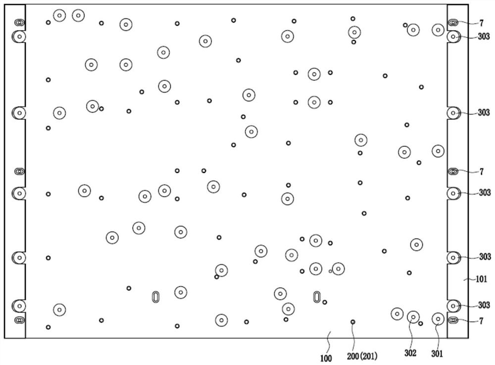
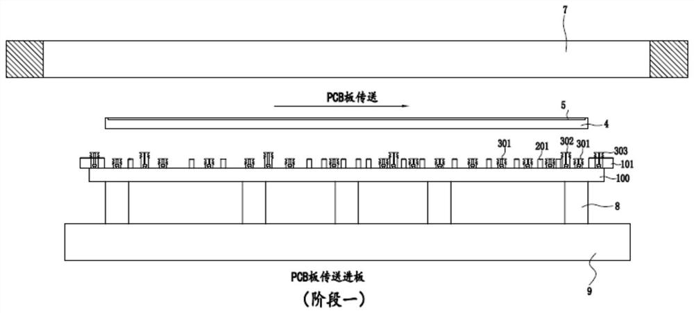
[0074] The supporting thimble 201 and the main platform 100 are integrally formed; in this embodiment, since the supporting thimble 201 and the main platform 100 can be made of the same material, during processing, the supporting thimble 201 and the main platform 100 It is processed into an integrated molding structure, which can facilitate processing and production on the one hand, so that the supporting thimble 201 and the main platform 100 do not need to be processed separately, and one-time molding can reduce processing time and improve processing efficiency; on the other hand, this can ensure that the supporting thimble 201 and the main platform The stability of the connection between 100 avoids the shaking of the supporting thimble 201 , so that the supporting thimble 201 can better support the PCB board 5 .

Embodiment 2

[0076] The bottom end of the support thimble 201 is fixed on the main body platform 100 by welding or riveting; in this embodiment, the support thimble 201 can be a commonly used standard thimble, so that the procurement sources are relatively abundant and the cost is low, and Welding and riveting processes are also mature processes in the industry, and their processing costs are also relatively low.

Embodiment 3

[0078] The main body platform 100 is provided with thimble mounting holes (not shown) having the same number as the supporting thimbles 201, the thimble mounting holes are adapted to the lower part of the supporting thimble 201, and the lower part of the supporting thimble 201 is inserted in the supporting thimble In the installation hole, and form transition fit or interference fit with the thimble installation hole; The support thimble 201 is plugged into the thimble mounting hole in a manner, and the support thimble 201 of the required height can be replaced according to the thickness of the tooling fixture 4 or the deformation amount of the bottom of the tooling fixture 4, so that the replacement of different support thimble 201 height requirements can be met.


PUM


Abstract

The invention discloses a vacuum platform for a printing machine and a using method of the vacuum platform, and relate to the technical field of printing machines. The vacuum platform for the printing machine comprises a main body platform, a supporting structure and a suction cup structure, the main body platform is fixed on a lifting workbench, the supporting structure comprises supporting ejector pins, and the suction cup structure comprises a PCB suction cup, a first steel mesh suction cup and a second steel mesh suction cup. When the vacuum platform is used, a PCB is jacked up through the supporting ejector pins, so that a gap is formed between the PCB and the inner bottom surface of a tool jig, and the PCB is prevented from being influenced by deformation of the bottom surface of the tool jig; then the PCB is adsorbed through the PCB suction cup, so that the PCB is tightly attached to the supporting ejector pins, and movement of the PCB is limited; a steel mesh is adsorbed through the first steel mesh suction cup and the second steel mesh suction cup, so that the steel mesh can be tightly and seamlessly attached to the PCB, then the phenomena of tin connection, tin shortage and the like of the PCB in the printing process are avoided, and the printing quality of the PCB can be effectively guaranteed.

Description

technical field [0001] The invention relates to the technical field of printing machines, in particular to a vacuum platform for printing machines and a method for using the same. Background technique [0002] During the production and processing of PCB boards, it is necessary to place the PCB boards in special tooling fixtures for processing, and paste high-temperature-resistant tapes on the PCB boards at the four corners of the tooling fixtures to fix the PCB boards. Then it is sent to the workbench of the solder paste printing equipment by the transmission mechanism for printing. After the solder paste is printed, it goes through patch and reflow soldering, and then tear off the high temperature resistant tape attached to the four corners of the PCB board, and then put it on The PCB board is taken out of the tooling fixture to complete the processing of the PCB board, and the tooling fixture is recycled again. Such production and processing methods have the following dis...

Claims


Application Information

Patent Timeline
Patent Type & Authority Applications(China)
IPC IPC(8): B41F15/20B41F15/16H05K3/12
CPCB41F15/20B41F15/16H05K3/1225
Inventor 俞元根
Owner HONGYI TECH AUTOMATION EQUIP HUIZHOU CO LTD
Learn More