
Penetrating and inserting combined type electroplating workpiece clamp

A workpiece fixture and insert group technology, applied in the direction of electrolysis components, electrolysis process, etc., can solve problems such as small problems, increased processing costs, and uneven obstacles, so as to improve the accuracy level, improve the operation efficiency, and improve the yield rate. Effect

Active Publication Date: 2021-12-03
翁健名 +1
View PDF3 Cites 0 Cited by
  • Summary
  • Abstract
  • Description
  • Claims
  • Application Information

AI Technical Summary

Problems solved by technology

[0004] The actual application of electroplating workpiece fixtures is criticized by people. The common point is that the accuracy error of the bending part of the metal plate is too large, because the position of the clamping point of the clamping and positioning member at the end of the stand part may be different. Due to the phenomenon of qualitative rebound of the part after bending or inaccurate welding alignment, there is an excessive offset error value. This error value may not be a big problem for a single point, but when a single electroplating workpiece requires When the number of multiple pins to be clamped is large, the cumulative result of multi-point error values ​​will cause obstacles in the process of installing the electroplating workpiece on the electroplating workpiece fixture, resulting in delays in the progress of electroplating operations and relatively high processing costs. , which is also a major problem faced by electroplating workpieces with double-pin and multi-pin forms during the electroplating process
[0005] Continuing from the previous paragraph, there may also be a problem of deformation of the electroplating workpiece. Because some electroplating workpieces are made of plastic and have too many slender and weak shapes, the overall shape rigidity is not good. When the position error value is too large, in order to install the electroplating workpiece on the electroplating workpiece fixture, the personnel must exert force to pull the off-position stand part to force it to be upright to achieve clamping. However, in this case, the immediate The elastic force accumulated when the frame is pulled will produce a rebound force after clamping to pull the electroplating workpiece to produce deformation (such as twisting, warping, etc.), and this deformation will occur after the electroplating workpiece is soaked in various chemical agents for electroplating. After the process, it may be stereotyped and difficult to restore, resulting in poor plating quality and defective electroplating workpieces (such as inaccurate fit when installed on the product), etc. The main reasons for not meeting the quality requirements of electroplating processing for high-precision electroplating workpieces
[0006] In terms of further derived problems, the aforementioned conventional electroplating workpiece fixtures cannot solve problems such as workpiece distortion and poor positioning accuracy. Then, when the industry wants to further introduce mechanical arms into the product electroplating assembly line to achieve high Efficiency in automatic assembly, obviously, there are bottlenecks and obstacles that are difficult to achieve, which leads to serious problems of difficulty in industrial upgrading

Method used


Image

  • Penetrating and inserting combined type electroplating workpiece clamp
  • Penetrating and inserting combined type electroplating workpiece clamp
  • Penetrating and inserting combined type electroplating workpiece clamp

Examples


Embodiment Construction

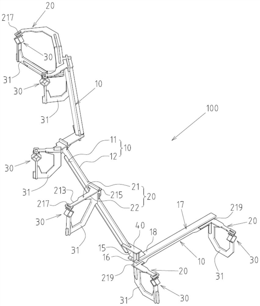
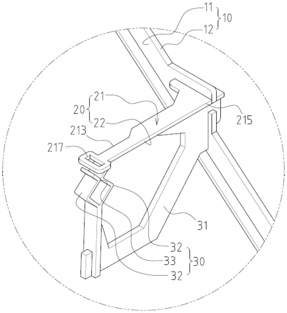
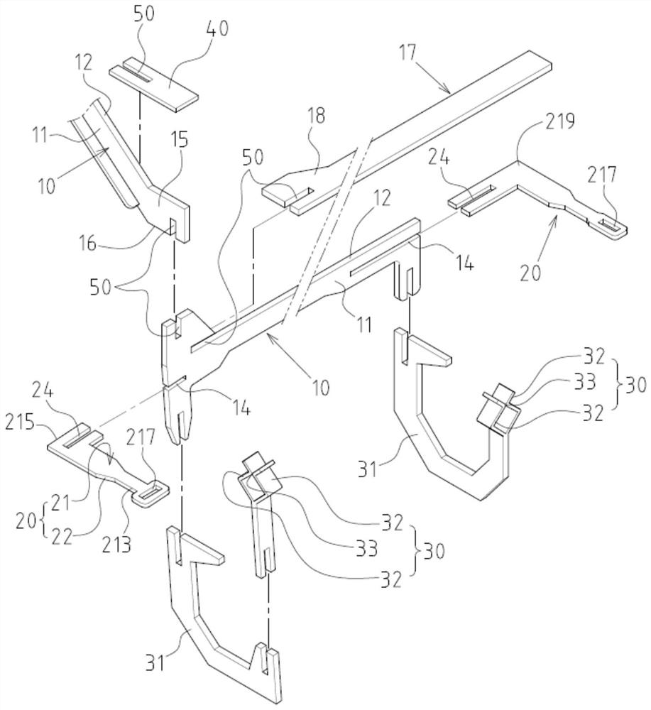
[0027] see Figure 1 to Figure 5 Shown is the preferred embodiment of the present invention for the plug-in plate combination electroplating workpiece fixture, but these embodiments are for illustration purposes only, and are not limited by this structure in the patent application.

[0028] The electroplating workpiece fixture 100 is used for inserting and clamping positioning of an electroplating workpiece 200 in a preset form (such as Figure 6 and Figure 7 As shown), the electroplating workpiece 200 is formed with a plurality of plug pins 201 for plugging into the electroplating workpiece fixture 100 .

[0029] The electroplating workpiece fixture 100 includes a main frame body 10 and a plurality of support plates 20 that are interfitted with each other, wherein the main frame body 10 includes two oppositely facing two frame surfaces 11 and one side edge 12 formed on the periphery of the two frame surfaces 11; Each bracket plate 20 includes an inserting plate surface 21 ...


PUM


Abstract

The invention discloses a penetrating and inserting combined type electroplating workpiece clamp. The penetrating and inserting combined type electroplating workpiece clamp mainly comprises a main frame body and a plurality of support plate pieces, wherein the main frame body and the support plate pieces are combined in an embedded and inserting mode, and the main frame body comprises two frame faces and a side edge formed on the peripheries of the two frame faces. Each support plate piece comprises an insertion plate surface and a side edge formed on the periphery of the insertion plate surface, the insertion plate surface faces the insertion group direction of insertion pins of an electroplated workpiece, the insertion plate surface comprises an insertion section and a combination section, the combination section is combined with the main frame body, the insertion section forms an alignment insertion hole for insertion of the insertion pins of the electroplated workpiece, a clamping and positioning part is arranged at the interval alignment position of each alignment insertion hole, and the clamping and positioning parts are combined and positioned on the main frame body or the support plate pieces in an embedded and inserted mode through an embedded and inserted type connecting arm.

Description

technical field [0001] The invention relates to a positioning frame body for electroplating; in particular, it refers to an innovative interspersed plug-in type electroplating workpiece fixture. Background technique [0002] The electroplating workpiece fixture referred to in the present invention is a positioning frame dedicated to installing and disposing the electroplating workpiece at a set position and angle, in order to achieve a better electroplating effect. [0003] For electroplating workpiece fixtures, the common form of the frame usually adopts the integral bending method of metal plates (note: because the required quantity is not large, the industry usually abandons stamping molds and adopts manual bending method) or the split type is welded. Combine to form the required horizontal frame part and vertical frame part, and then set a clamping and positioning member at the end of the vertical frame part for clamping at the preset foot position of the electroplating ...

Claims


Application Information

Patent Timeline
Patent Type & Authority Applications(China)
IPC IPC(8): C25D17/08
CPCC25D17/08
Inventor 翁健名王家财
Owner 翁健名
Learn More