Coal feeding system for coal pulverizing system of thermal power plant

A thermal power plant and pulverizing system technology, applied in the direction of block/powder supply/distribution, combustion method, combustion equipment, etc., can solve the problem of inability to ensure stable combustion of boilers, failure to ensure peak output of units, and influence on safe and stable operation of units and other issues, to achieve the effect of stable and safe combustion, safe and reliable opening size, safe and reliable

Pending Publication Date: 2021-12-03
SHANDONG RIZHAO POWER GENERATION CO LTD
View PDF6 Cites 1 Cited by
  • Summary
  • Abstract
  • Description
  • Claims
  • Application Information

AI Technical Summary

Problems solved by technology

However, with the change and development of the power industry, thermal power plants often cycle from full load to 50% load or even 25% load to full load within a day, and the coal into the furnace is the same as the previous single blending method. When the load is low, the combustion stability of the boiler cannot be guaranteed, and the peak output of the unit cannot be guaranteed when the load is high. This hidden danger has been fully exposed in the actual production process, which greatly affects the safe and stable operation of the unit.
[0003] The raw coal bunker of Huaneng Rizhao Power Plant’s pulverizing system is designed in a conical shape with a large top and a small bottom. A vertical section coal pipe is connected to the lower opening. A horizontal pull-out coal gate driven by a single electric actuator is installed under the coal drop pipe. The control of the existing coal gate can only meet the two commands of full open and full close, and the coal feeder driven by the lower frequency conversion motor changes the amount of coal delivered to the coal mill

Method used


Image

  • Coal feeding system for coal pulverizing system of thermal power plant
  • Coal feeding system for coal pulverizing system of thermal power plant
  • Coal feeding system for coal pulverizing system of thermal power plant

Examples


Embodiment Construction

[0029] In order to make the purpose, technical solutions and advantages of the embodiments of the present invention clearer, the technical solutions of the present invention will be clearly and completely described below in conjunction with the accompanying drawings. Obviously, the described embodiments are part of the embodiments of the present invention, not all of them. the embodiment. Based on the embodiments of the present invention, all other embodiments obtained by persons of ordinary skill in the art without making creative efforts belong to the protection scope of the present invention.

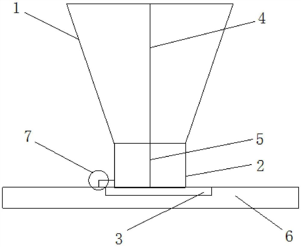
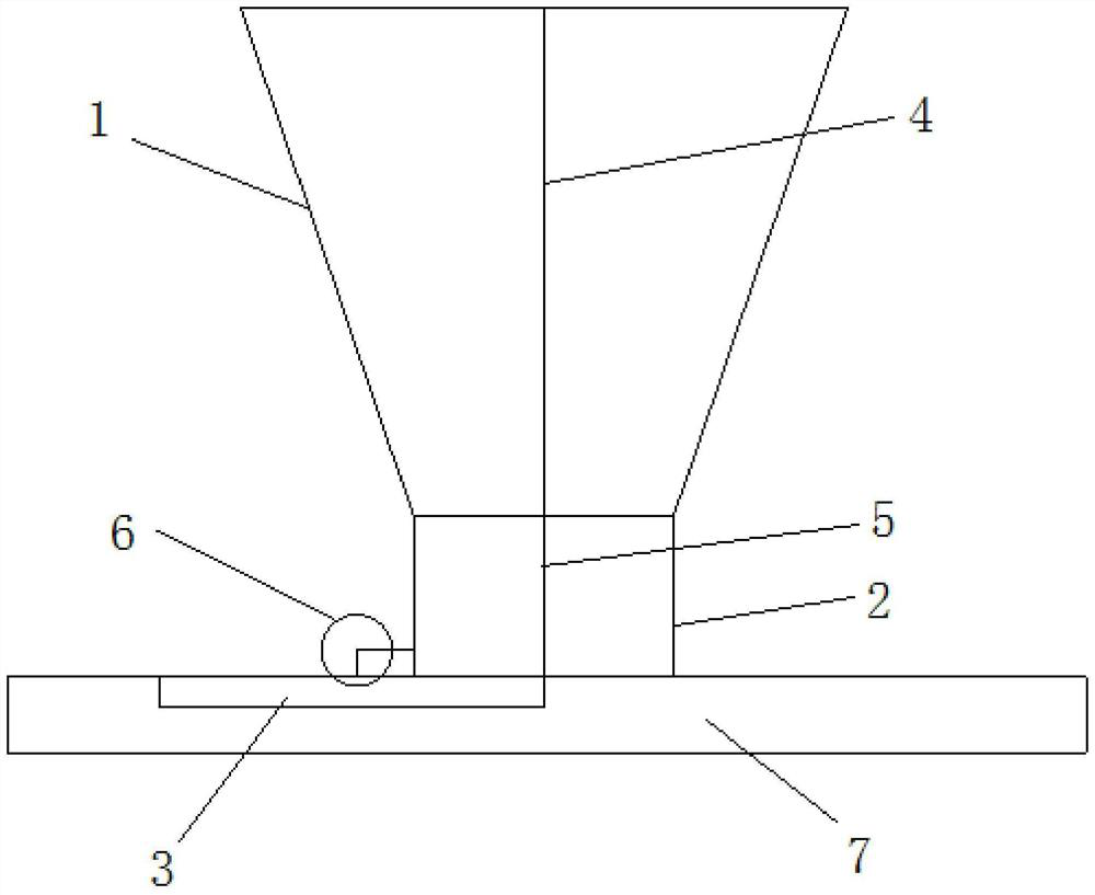
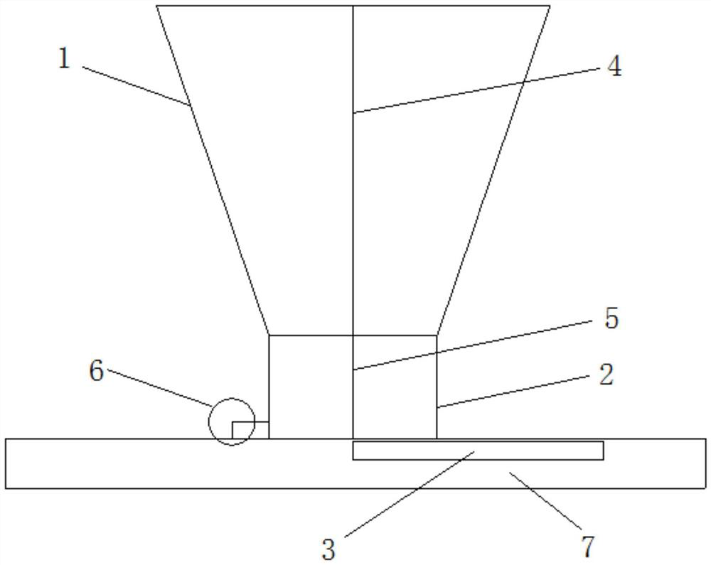
[0030] As a specific embodiment of the present invention, a coal feeding system for a pulverizing system of a thermal power plant includes a raw coal bunker 1, which is in the shape of a truncated cone with a large upper part and a smaller lower part. The outlet end of the raw coal bunker 1 is connected with a coal drop pipe 2 , preferably, the diameter of the coal drop pipe 2 is the...


PUM


Abstract

The invention discloses a coal feeding system for a coal pulverizing system of a thermal power plant. The coal feeding system comprises a raw coal bunker, a coal falling pipe is connected to the outlet end of the raw coal bunker, a coal feeding gate capable of reciprocating at any opening degree is slidably arranged at the outlet end of the coal falling pipe, a first vertical partition plate used for partitioning the coal bunker is arranged in the raw coal bunker, a vertical second partition plate used for separating coal pipes is arranged in the coal falling pipe, and the first partition plate and the second partition plate are located on the same plane. According to the coal feeding system, the coal quality of coal as fired can be selected autonomously and flexibly, the problem that an existing coal pulverizing system can only use a single coal type blended according to a coal yard is eliminated, stable and safe boiler combustion in the existing and recent power development stage is guaranteed, the capacity of the thermal power plant for rapidly responding to power grid load increasing and decreasing is greatly guaranteed, and a reliable guarantee is provided for the safety of a power system.

Description

technical field [0001] The invention belongs to the technical field of thermal power generation, and in particular relates to a coal feeding system for a pulverizing system of a thermal power plant. Background technique [0002] Due to some disadvantages such as poor sustainability, frequent changes, and poor stability of new energy power generation forms, the larger their proportion in the entire power generation system, the higher the requirements and challenges for other traditional power generation forms. Therefore, thermal power plants are being transformed to meet the needs of power grid peak regulation and frequency regulation. Among them, coal-fired power plants are the main form of thermal power plants in my country. The coal fired in thermal power plants is usually called thermal coal. Its technical indicators mainly include moisture, ash, volatile matter, calorific value, ignition temperature, grindability, etc. These indicators are closely related to the combust...

Claims


Application Information

Patent Timeline
Patent Type & Authority Applications(China)
IPC IPC(8): F23K3/00F23K3/22
CPCF23K3/00F23K3/22
Inventor 李守磊董兆杰鲁统浩孙树人徐潇悦张瑾
Owner SHANDONG RIZHAO POWER GENERATION CO LTD
Why Eureka
Try Eureka