
A fully automatic magnetic compensation method for atomic spin gyroscope based on pid algorithm

A kind of atomic spin and gyroscope technology, applied in instruments, electric controllers, controllers with specific characteristics, etc., can solve the problems of low accuracy, complicated operation, long compensation time, etc., to improve the compensation accuracy and collect data accurately , the effect of volume reduction

Active Publication Date: 2022-06-17
BEIHANG UNIV
View PDF15 Cites 0 Cited by
  • Summary
  • Abstract
  • Description
  • Claims
  • Application Information

AI Technical Summary

Problems solved by technology

[0004] The technical problem to be solved in the present invention is: to solve the manual magnetic compensation method of the traditional SERF atomic spin gyroscope, it is necessary to observe the steady-state output of the gyroscope through instruments such as signal generators and oscilloscopes, and provide the step amount based on experience to adjust the compensation axis magnetic field, resulting in Problems of low precision, cumbersome operation and long compensation time

Method used


Image

  • A fully automatic magnetic compensation method for atomic spin gyroscope based on pid algorithm
  • A fully automatic magnetic compensation method for atomic spin gyroscope based on pid algorithm
  • A fully automatic magnetic compensation method for atomic spin gyroscope based on pid algorithm

Examples


Embodiment Construction

[0046] The technical solutions in the embodiments of the present invention will be clearly and completely described below with reference to the accompanying drawings in the embodiments of the present invention. Obviously, the described embodiments are only a part of the embodiments of the present invention, rather than all the embodiments. Based on the embodiments of the present invention, all other embodiments obtained by those of ordinary skill in the art without creative efforts shall fall within the protection scope of the present invention.

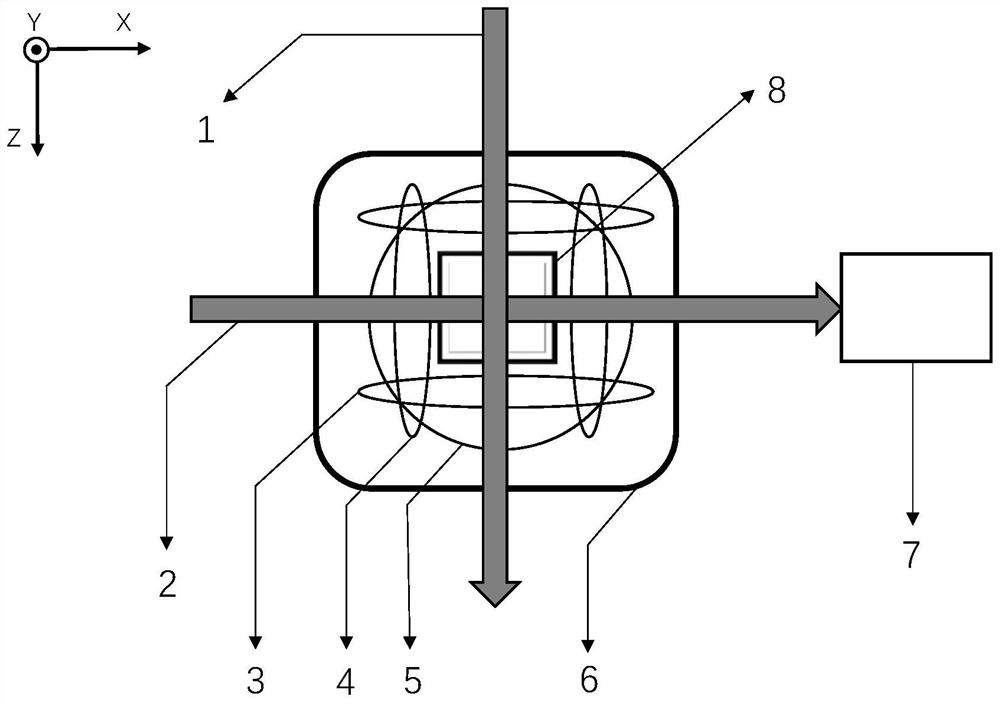
[0047] figure 1 It is a schematic diagram of the system framework of the present invention, and the Z axis is defined as the pumping light direction of the gyroscope, the X axis is the detection light direction orthogonal to it, and the Y axis is the perpendicular direction to the detection light and the pumping light. Among them, 1 represents the pumping laser in the Z-axis direction, 2 represents the detection laser in the X-axis d...


PUM


Abstract

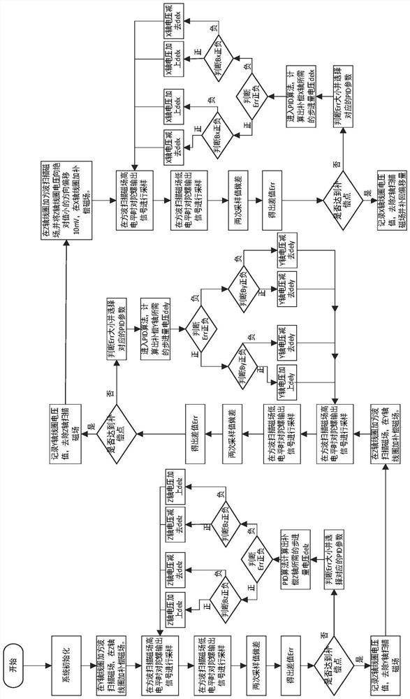
The invention relates to a fully automatic magnetic compensation method for a SERF atomic spin gyroscope based on a PID algorithm. This method performs three-axis magnetic compensation in a fully automatic sequence. First, a square wave scanning signal is loaded on the scanning axis coil, and the steady-state values ​​of the two gyroscope output signals caused by the high and low levels of the scanning axis coil square wave are collected and filtered. Finally, the difference between the two steady-state values ​​is made, and the PID algorithm is applied to the difference, and the PID parameters are automatically assigned according to the difference, and the difference at this moment and the difference at the previous moment are substituted into the PID algorithm to calculate a step voltage. And load the step amount to the compensation axis, repeat the above steps until the steady-state difference of the gyro output approaches zero and enters the error zone, then the magnetic field of the compensation axis coil reaches the compensation point, the single-axis compensation ends, and the next axis compensation starts. This method is automatically executed by the algorithm for three-axis magnetic field compensation, and each axis can be compensated to the zero magnetic compensation point. Compared with manual magnetic compensation, the speed is faster, the accuracy is better than 0.1nT, the operation is simple, and the volume is smaller.

Description

technical field [0001] The invention relates to an automatic magnetic compensation method for a SERF (Spin-Exchange-Relaxation-Free) atomic spin gyroscope based on a PID algorithm, which is applied to the field of active magnetic compensation of a SERF atomic spin gyroscope, and can rapidly Compensating the magnetic field of the SERF atomic spin gyroscope to the zero magnetic state provides the necessary conditions for the normal operation of the SERF atomic spin gyroscope. Background technique [0002] Aviation, aerospace, autopilot and other fields have an urgent need for high-precision inertial navigation, and the gyroscope is the core component of the inertial navigation system. The performance of the gyroscope directly determines the overall performance of the inertial navigation system. Atomic gyroscopes are considered to be an important development direction of a new generation of ultra-high-precision gyroscopes, and SERF atomic spin gyroscopes have been verified to h...

Claims


Application Information

Patent Timeline
Patent Type & Authority Patents(China)
IPC IPC(8): G01C25/00G05B11/42
CPCG01C25/005G05B11/42
Inventor 周新秀曹朝扬范文峰崔培玲毛琨
Owner BEIHANG UNIV
Learn More