Self-balancing interface bonding performance single shear test system and test method thereof
An interfacial bonding, self-balancing technology, applied in the direction of using a stable shear force to test the strength of materials, measuring devices, strength characteristics, etc. It is exactly the same, and cannot be directly clamped on the testing machine, etc., to achieve effective and accurate testing, reliable testing systems and implementation methods, and accurate and reliable test results.
- Summary
- Abstract
- Description
- Claims
- Application Information
AI Technical Summary
Problems solved by technology
Method used
Image

Examples
Embodiment Construction
[0064] The specific implementation of the test system of the present invention will be further described in detail below in conjunction with the accompanying drawings.
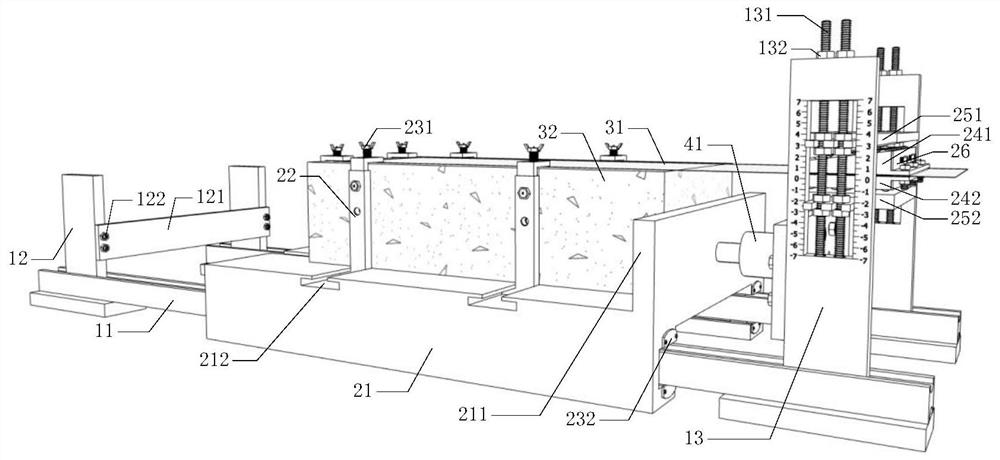
[0065] Such as figure 1 As shown in Fig. 1, a self-balancing single-shear test system for interfacial adhesion performance includes a support device with slide rails, an anchor device, a test piece and a force application device.
[0066] The bracket device is composed of a double-running slide rail 11, a left bracket 12 and a right bracket 13. The double-running slide rail 11 mainly provides a track for the trolley 21, the right bracket 13 is used for fixing the anchoring device, and the left bracket 12 is used to prevent the trolley 21 from slipping out , a pair of left brackets 12 are installed on one side of the double running slide rail 11, the buffer pad 121 is located between the pair of left brackets 12; a pair of right brackets 13 are installed on the other side of the double running slide rail 11, a...
PUM
 Abstract
Description
Claims
Application Information
 - Generate Ideas
- Intellectual Property
- Life Sciences
- Materials
- Tech Scout
- Unparalleled Data Quality
- Higher Quality Content
- 60% Fewer Hallucinations
Browse by: Latest US Patents, China's latest patents, Technical Efficacy Thesaurus, Application Domain, Technology Topic, Popular Technical Reports.
© 2025 PatSnap. All rights reserved.Legal|Privacy policy|Modern Slavery Act Transparency Statement|Sitemap|About US| Contact US: help@patsnap.com