
Fuel cell system

A fuel cell system and fuel cell technology, applied in the direction of fuel cells, fuel cell additives, circuits, etc., can solve the problems that the cathode waste gas energy cannot be recycled, it is not enough to independently drive the air compressor, and the cost is high

Pending Publication Date: 2021-12-03
ROBERT BOSCH GMBH
View PDF0 Cites 0 Cited by
  • Summary
  • Abstract
  • Description
  • Claims
  • Application Information

AI Technical Summary

Problems solved by technology

However, this structure using cathode exhaust gas is very complicated and costly; in addition, the mechanical energy generated by cathode exhaust gas is not enough to independently drive the air compressor, and can only function as a supplement to the motor
[0005] In addition, some existing fuel cell systems do not have a structure for reusing the cathode exhaust gas at all, and the energy of the cathode exhaust gas cannot be recycled

Method used


Image

  • Fuel cell system
  • Fuel cell system
  • Fuel cell system

Examples


Embodiment Construction

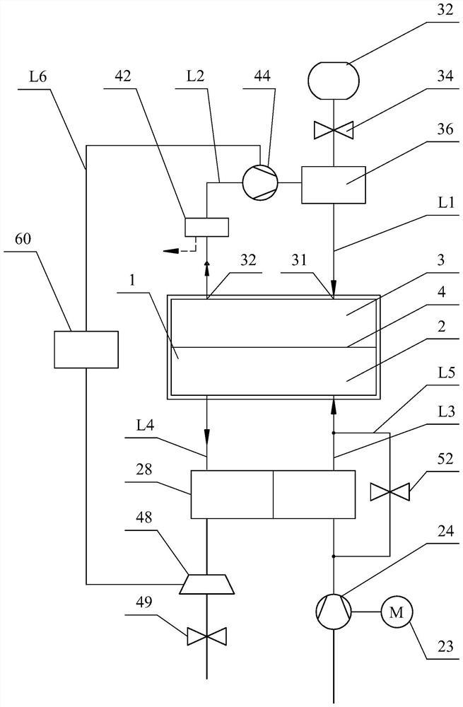
[0020] Refer below figure 1 A first exemplary embodiment of the present invention is described in more detail.

[0021] Such as figure 1 As shown, the fuel cell system according to the exemplary embodiment firstly comprises a fuel cell 1 with a cathode chamber 2 and an anode chamber 3 which are separated from each other by a proton-conducting or electrolyte membrane 4 . In this fuel cell, the cathode chamber 2 is supplied with air, and the anode chamber 3 is supplied with fuel gas. Oxygen in the air and hydrogen in the fuel gas undergo a chemical reaction inside the fuel cell 1 to generate electricity. In this application, the fuel gas may be hydrogen or other hydrogen-containing gas.

[0022] Fuel gas from a fuel gas source 32 is supplied to the anode chamber 3 via a fuel gas supply line L1 on which a fuel gas supply valve 34 and a fuel gas injection device 36 are provided. The fuel gas source 32, such as a hydrogen tank, stores high-pressure fuel gas, and after the high-p...


PUM


Abstract

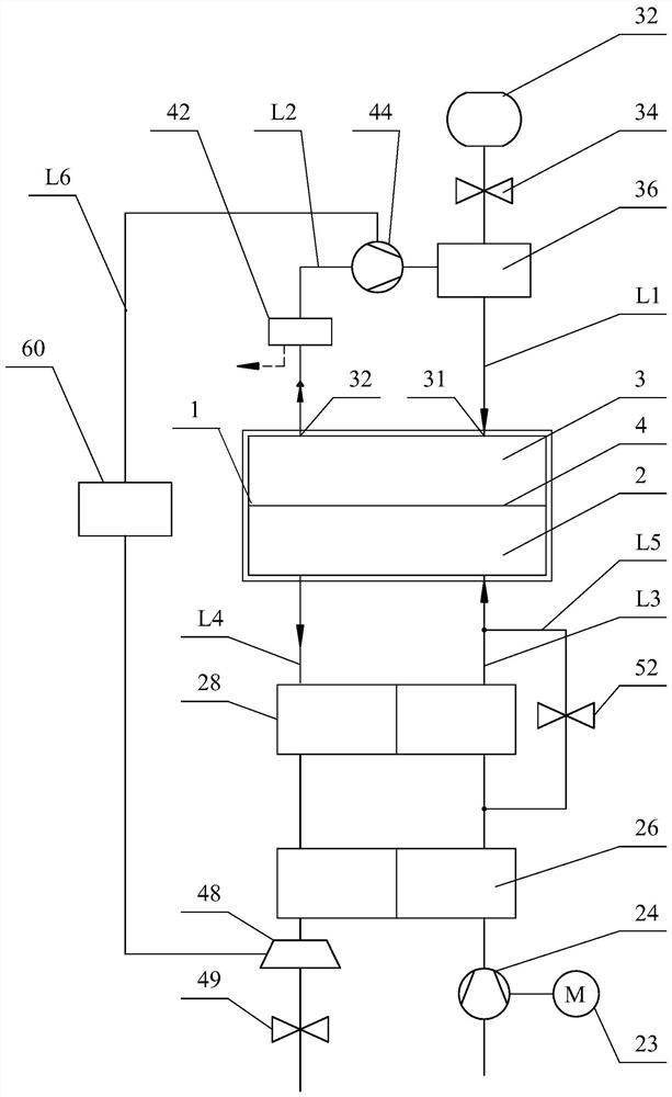
The present application relates to a fuel cell system. The fuel cell system comprises a fuel cell (1) having a cathode chamber (2) and an anode chamber (3), a fuel gas supply line (L1) used for supplying a fuel gas to the anode chamber (3) and provided with a fuel gas injection device (36), a fuel gas recirculation line (L2) used for introducing a recirculation stream exiting the anode chamber (3) into the fuel gas supply line (L1) so as to enable the recirculation stream to reenter the anode chamber (3) of the fuel cell (1) and provided with a recirculation device (44), an air supply line (L3) used for supplying air to the cathode chamber (2) and provided with an air supply device (24), and an exhaust gas discharge line (L4) used for discharging an exhaust gas stream discharged from the cathode chamber (2) of the fuel cell and provided with an energy storage device. The fuel cell system further comprises an energy transfer path (L6) for transferring energy accumulated by the energy storage device from the exhaust gas stream to the fuel gas recirculation line (L2).

Description

technical field [0001] The present application relates to a fuel cell system, in particular to a fuel cell system capable of making full use of exhaust gas discharged from the fuel cell. Background technique [0002] In general, like an electrochemical device that chemically reacts hydrogen and oxygen to generate electricity, a fuel cell refers to a system that continuously generates electricity by supplying a fuel gas such as hydrogen and an oxidant such as air to an anode and a cathode, respectively. A fuel cell includes the above-mentioned cathode and anode, and an electrolyte membrane disposed between the cathode and the anode. [0003] The anode of the fuel cell is supplied with fuel gas, and the cathode is supplied with air. The hydrogen in the fuel passes through the electrolyte membrane and reacts with the oxygen in the air in the cathode chamber to generate electricity, and at the same time generates product water. The generated water and unreacted excess Oxygen an...

Claims


Application Information

Patent Timeline
IPC IPC(8): H01M8/04082H01M8/04089H01M8/04111H01M8/04119
CPCH01M8/04097H01M8/04111H01M8/04149H01M8/04201Y02E60/50
Inventor 周卫
Owner ROBERT BOSCH GMBH
Learn More