
Dipole ground penetrating radar antenna and ground penetrating radar system

A ground penetrating radar and dipole technology, which is applied in the direction of the connection of the antenna grounding switch structure, the resonant antenna, and the mid-position feed between the antenna terminals. The current size of the two arms of the sub-arm is different, so as to facilitate the outdoor drilling test, improve the adaptation performance, and balance the feeding effect.

Pending Publication Date: 2021-12-03
XI AN JIAOTONG UNIV
View PDF10 Cites 0 Cited by
  • Summary
  • Abstract
  • Description
  • Claims
  • Application Information

AI Technical Summary

Problems solved by technology

[0006] Aiming at the technical problems existing in the prior art, the present invention provides a dipole ground penetrating radar antenna and a ground penetrating radar system to solve the problem that the two arms of the dipole appear when the coaxial cable is used to feed the antenna. The magnitude of the current on the antenna is not equal, and it is easy to change the pattern of the antenna, so that the technical problem of the mismatch between the feeder and the antenna

Method used


Image

  • Dipole ground penetrating radar antenna and ground penetrating radar system
  • Dipole ground penetrating radar antenna and ground penetrating radar system
  • Dipole ground penetrating radar antenna and ground penetrating radar system

Examples


Embodiment

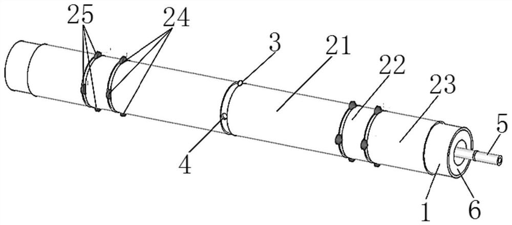
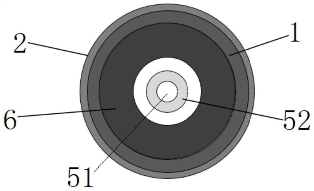
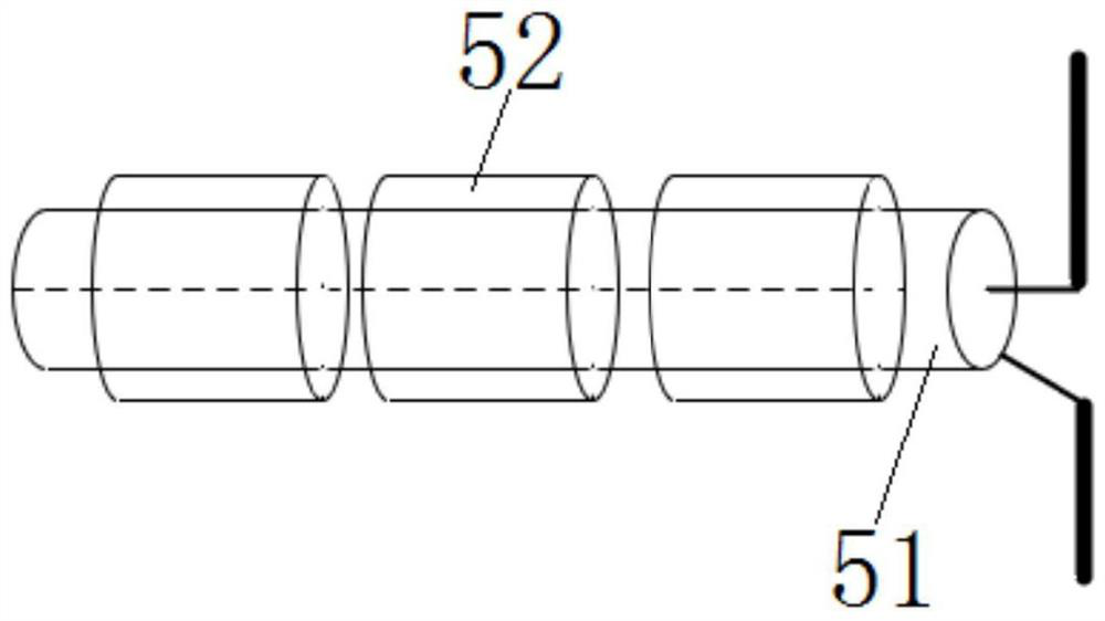
[0045] as attached Figure 1-3 As shown, this embodiment provides a dipole ground penetrating radar antenna, including a fixed tube 1, two dipole units 2, a loading resistor 3 and a coaxial cable 5; the two dipole units are symmetrically sleeved On the outside of the fixed tube 1, a gap is provided between the two dipole units 2; a feed hole 4 is provided at the gap between the two dipole units 2, and the feed hole 4 serves as two dipole units 2; the coaxial feed 5 is set through the fixed tube 1 to form a new balun structure; one end of the coaxial cable 5 passes through the feed hole 4 and is respectively connected to the two dipole units 2, Connect the other end to the signal source.

[0046] Each dipole unit 2 includes a first dipole section 21, a second dipole section 22, a third dipole section 23, four first resistors 24 and four A second resistor 25; wherein, the first dipole section 21 is arranged near the middle of the fixed pipe 1, and the third dipole section 23 i...


PUM

PropertyMeasurementUnit
Outer diameteraaaaaaaaaa
Lengthaaaaaaaaaa
Lengthaaaaaaaaaa

Abstract

The invention discloses a dipole ground penetrating radar antenna and a ground penetrating radar system. The dipole ground penetrating radar antenna comprises a fixing pipe, two dipole units symmetrically sleeve the outer side of the fixing pipe, and a feed hole is formed in a gap between the two dipole units; a coaxial cable is arranged in the fixing pipe in a penetrating manner, one end of the coaxial cable penetrates through the feed hole and then is connected with the two dipole units, and the other end of the coaxial cable is connected with a signal source; and the coaxial cable comprises a coaxial cable body and a plurality of ferrite magnetic rings, and the plurality of ferrite magnetic rings are sequentially and continuously arranged on the outer side of a coaxial cable body in a sleeving manner. According to the dipole ground penetrating radar antenna and the ground penetrating radar system of the invention, the coaxial cable passes through the fixing pipe to form a novel balun structure; and according to the coaxial cable, the ferrite magnetic rings are arranged on the outer side of the coaxial cable body, the high-resistance choke function of the ferrite magnetic ring is utilized, current on arms of the dipole units is effectively prevented from flowing to the outer side surface of the coaxial cable, it is ensured that the current on the two arms of the dipole units is equal, balanced feed is achieved, distortion of an antenna directional pattern is avoided, and an omnidirectional antenna is realized.

Description

technical field [0001] The invention belongs to the technical field of antennas, in particular to a dipole ground-penetrating radar antenna and a ground-penetrating radar system. Background technique [0002] Borehole radar is a branch of ground penetrating radar. Its principle is to use the receiving antenna to receive the electromagnetic wave radiated by the transmitting antenna from the detection target, so as to receive the signal to analyze the underground situation; because of its high-resolution imaging capability, long detection distance and The structure is simple and widely used; now, drilling radar technology has been widely used in oil detection, geological survey and mineral deposit detection and other fields. [0003] As an important part of the ground penetrating radar system to send and receive signals, the antenna plays a key role in the detection performance of the entire system; for example, the effective working bandwidth of the antenna must be wide enoug...

Claims


Application Information

Patent Timeline
IPC IPC(8): H01Q1/38H01Q1/50H01Q9/16
CPCH01Q1/38H01Q1/50H01Q9/16Y02A90/30
Inventor 张安学王亚飞刘昌斌王力师振盛
Owner XI AN JIAOTONG UNIV
Learn More