New energy automobile cleaning equipment and cleaning method
A technology for new energy vehicles and cleaning equipment, which is applied in vehicle cleaning equipment, vehicle cleaning, and vehicle exterior cleaning devices, etc. The effect of a large spray area
- Summary
- Abstract
- Description
- Claims
- Application Information
AI Technical Summary
Problems solved by technology
Method used
Image
Examples
Embodiment 1
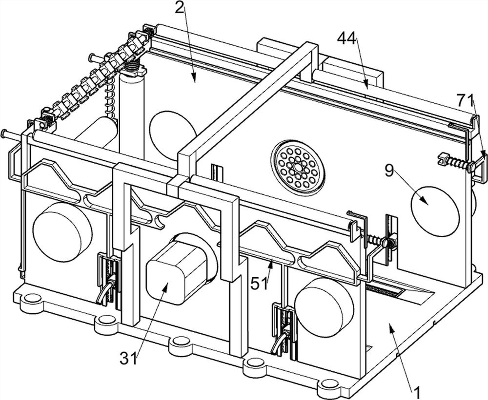
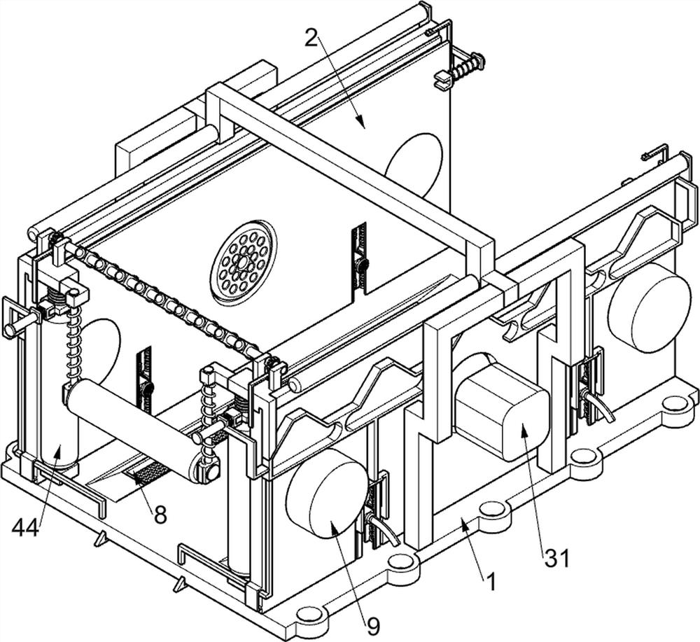
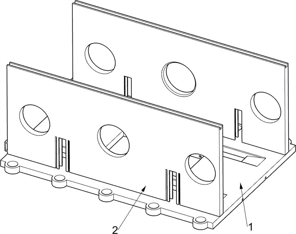
[0043] Cleaning equipment and cleaning methods for new energy vehicles, such as figure 1 , figure 2 , image 3 , Figure 4 , Figure 5 , Image 6 , Figure 7 , Figure 8 with Figure 9 As shown, it includes a bottom plate 1, a slotted mounting plate 2, a spray washing assembly 3 and a water collection assembly 4. The upper part of the bottom plate 1 is symmetrically fixed with a slotted mounting plate 2, and the bottom plate 1 is provided with a spray washing assembly 3. The spray washing assembly 3 is used to fully and comprehensively wash the new energy vehicle, and the bottom plate 1 is provided with a water collection assembly 4, and the water collection assembly 4 is used to dry the surface of the new energy vehicle after cleaning.
[0044] The spray cleaning assembly 3 includes a large high-pressure nozzle 31, a water storage tank 32, a high-pressure nozzle group 1 33, a downward pressure slide rail frame 34, a first return spring 36 and a small high-pressure noz...
Embodiment 2
[0048] On the basis of Example 1, such as Figure 9 , Figure 10 with Figure 11 As shown, it also includes a swing assembly one 5, the swing assembly one 5 is arranged on the down-pressing slide rail frame 34, and the swing assembly one 5 is used to make the high-pressure nozzle group two 47 fully wash the upper cover surface of the new energy vehicle, The swing assembly one 5 includes a wedge-shaped lower pressing frame 51, a fixed rack frame one 52, a fixed rack frame two 53, an adjustment gear one 54, an L-shaped rack frame 55 and an adjustment gear two 56, a pair of lower gears positioned at the front side The upper part of the pressure slide rail frame 34 is jointly fixedly connected with a wedge-shaped lower pressure frame 51, and the upper part of the wedge-shaped lower pressure frame 51 adopts a double-slope structure. Due to the effect of the wedge-shaped lower pressure frame 51, the wedge-shaped shaft frame 43 and its upper device will reciprocate up and down. A p...
Embodiment 3
[0051] On the basis of Example 2, such as Figure 12 , Figure 13 with Figure 14As shown, it also includes a swing assembly 2 6, which is used to increase the injection area of the high-pressure nozzle group 1 33 on the new energy vehicle chassis. Lower pressing frame 61, first homing spring 62, wedge-shaped sliding rack rack 63, second homing spring 64 and adjustment gear three 65, the left side of the slotted mounting plate 2 bottom slidingly connected with Z-type lower pressing frame 61, On the same side, the bottom of the Z-shaped lower pressure frame 61 and the wedge-shaped lower pressure frame 51 are fixedly connected, the first return spring 62 is connected between the Z-shaped lower pressure frame 61 and the slotted mounting plate 2, and a pair of wedge-shaped The sliding rack frame 63, the wedge-shaped sliding rack frame 63 passes through the water storage tank 32, the second homing spring 64 is connected between the wedge-shaped sliding rack frame 63 and the bot...
PUM
 Abstract
Description
Claims
Application Information
 - R&D
- Intellectual Property
- Life Sciences
- Materials
- Tech Scout
- Unparalleled Data Quality
- Higher Quality Content
- 60% Fewer Hallucinations
Browse by: Latest US Patents, China's latest patents, Technical Efficacy Thesaurus, Application Domain, Technology Topic, Popular Technical Reports.
© 2025 PatSnap. All rights reserved.Legal|Privacy policy|Modern Slavery Act Transparency Statement|Sitemap|About US| Contact US: help@patsnap.com


