
Water level buoyancy automatic drainage fuel filter

A fuel filter and automatic drainage technology, which is applied to engine components, machines/engines, liquid fuel feeders, etc., can solve the problems that water cannot be discharged directly, damage to the engine or surrounding parts, and excessive water accumulation

Inactive Publication Date: 2021-12-07
芜湖冠东工业技术有限公司
View PDF0 Cites 0 Cited by
  • Summary
  • Abstract
  • Description
  • Claims
  • Application Information

AI Technical Summary

Problems solved by technology

[0003] This kind of filter needs to be drained manually. If it is not drained in time for a long time, water entering the engine will cause great harm to the engine.
[0004] The separated water may still contain dissolved oil components, so the separated water cannot be discharged directly, otherwise it will affect the environment. The best way is to let the accumulated water discharge by itself and use the heat of the car's own engine and the wind speed during driving to control the accumulation. However, under special conditions, such as poor fuel quality and a lot of water, there is still the possibility of too much water, so that too much water can not be volatilized in time, overflowing from the vent hole may affect the engine or Peripheral parts are damaged

Method used


Image

  • Water level buoyancy automatic drainage fuel filter
  • Water level buoyancy automatic drainage fuel filter
  • Water level buoyancy automatic drainage fuel filter

Examples


Embodiment Construction

[0035] Preferred embodiments of the present invention will be described in detail with reference to the accompanying drawings so that those embodiments can be easily realized by those having ordinary skill in the art to which the invention pertains. However, the present invention can also be realized in various forms, so the present invention is not limited to the embodiments described hereinafter. In addition, in order to describe the invention more clearly, parts that are not connected with the present invention will be omitted from the drawings.

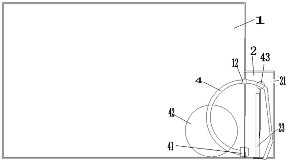
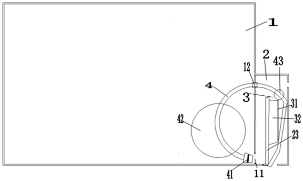
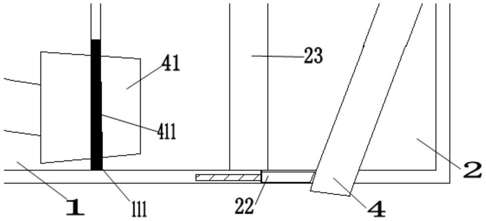
[0036] A water level buoyancy automatic drainage fuel filter, comprising: a first cavity 1, a second cavity 2, a third cavity 3, and a movable round rod 4;

[0037] Such as figure 1 , figure 2 As shown, the first cavity 1 includes: a water outlet hole 11, a water outlet magnet 111, and a movable shaft 12;

[0038] The first cavity 1 is cylindrical, and two circular openings are vertically arranged on the cylindrical arc surfac...


PUM


Abstract

The invention relates to the field of drainage of fuel filters, in particular to a water level buoyancy automatic drainage fuel filter. The water level buoyancy automatic drainage fuel filter comprises a first cavity, a second cavity, a third cavity and a movable round rod. The second cavity is a cylinder provided with a crescent notch from top to bottom, the crescent notch on the inner side is tightly attached to the side face of the first cavity, and the bottom of the crescent notch and the bottom of the first cavity are on the same horizontal plane. The problems that an engine or peripheral parts are damaged and the environment is destroyed due to manual emission and untimely emission are solved.

Description

technical field [0001] The invention relates to the field of fuel oil filter drainage, in particular to a water level buoyancy automatic drainage fuel filter. Background technique [0002] Because the moisture in the fuel will be deposited under the fuel, the traditional fuel drain filter includes a filter housing, an opening is arranged on the filter housing, a connecting plate is installed at the opening, and an oil outlet is arranged in the middle of the connecting plate. The connecting plate is regularly provided with an oil inlet port around the oil outlet, and the top of the filter housing is provided with a crimp that clamps the connecting plate, and a sealing ring is provided on the crimp to seal the opening on the connecting plate. A filter element is arranged in the housing, the upper part of the filter element is offset against the connecting plate, and a supporting spring is pressed between the lower part and the filter housing for positioning, and the bottom of ...

Claims


Application Information

Patent Timeline
Patent Type & Authority Applications(China)
IPC IPC(8): F02M37/24
CPCF02M37/24
Inventor 陈庚朱子韬赵金麒
Owner 芜湖冠东工业技术有限公司
Learn More