Pulling force stepless regulation counterweight power generation mechanism and body builder with same

A technology of stepless adjustment and generator, applied in the direction of the mechanism, collector, machine/engine, etc. that generate mechanical power, it can solve the problems of inability to meet accurate adjustment, cumbersome tension adjustment process, inability to adjust the tension size, etc., and achieve convenient transportation. The effect of installation, weight reduction, and compact device structure

Pending Publication Date: 2021-12-07
SHANGHAI YINSHENG TECH CO LTD
View PDF9 Cites 0 Cited by
  • Summary
  • Abstract
  • Description
  • Claims
  • Application Information

AI Technical Summary

Problems solved by technology

[0003] This structure has many disadvantages. For example, this kind of counterweight structure needs to preset a lot of counterweights, which makes the weight of the fitness equipment itself very large, and the tension adjustment process is cumbersome. It needs to be operated in a static state of the fitness equipment. Insert the counterweight through the tension rod to achieve the purpose of fixing. Every time the adjustment process needs to be adjusted by inserting and pulling out the bolt, there will be problems such as difficult insertion of the bolt and high friction during the insertion process; and the weight of the existing fitness equipment is fixed. To adjust the tension, you can only choose a fixed tension value, and it is impossible to adjust any tension, and it cannot meet the accurate adjustment of the tension range during the fitness process, etc., and it does not collect various kinetic energy generated during the fitness process. Therefore, it is necessary to design a A new type of regulating mechanism

Method used


Image

  • Pulling force stepless regulation counterweight power generation mechanism and body builder with same
  • Pulling force stepless regulation counterweight power generation mechanism and body builder with same
  • Pulling force stepless regulation counterweight power generation mechanism and body builder with same

Examples


Embodiment Construction

[0029] In order to make the purpose, technical solutions and advantages of the embodiments of the present invention clearer, the technical solutions in the embodiments of the present invention will be clearly and completely described below in conjunction with the drawings in the embodiments of the present invention. Obviously, the described embodiments It is a part of embodiments of the present invention, but not all embodiments. Based on the embodiments of the present invention, all other embodiments obtained by persons of ordinary skill in the art without creative efforts fall within the protection scope of the present invention.

[0030] Embodiments of the present invention are described in detail below, and examples of the embodiments are shown in the drawings, wherein the same or similar reference numerals denote the same or similar elements or elements having the same or similar functions throughout. In describing the present invention, it should be understood that the t...


PUM


Abstract

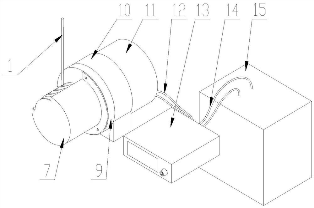
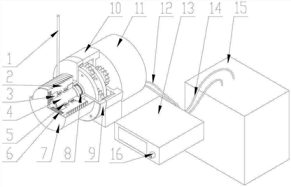
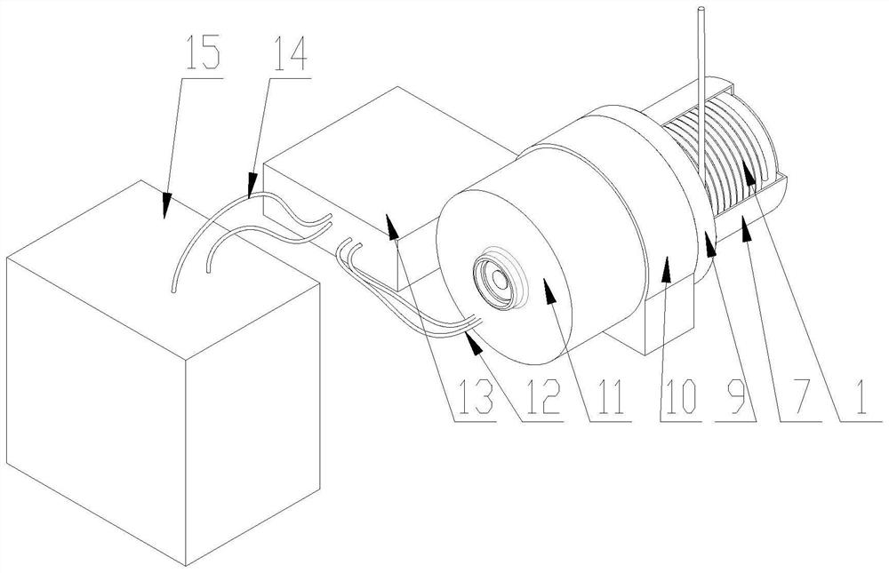
The invention discloses a pulling force stepless regulation counterweight power generation mechanism and a body builder with the same. The pulling force stepless regulation counterweight power generation mechanism comprises a pulling rope, a winding drum, a mounting seat, a central shaft, a spring, a power generator and a regulator. One end of the pulling rope is connected with the winding drum, and one part of the pulling rope is wound on the peripheral wall of the winding drum. The winding drum is rotationally connected with the mounting seat, the outer end of the spring is connected with the winding drum, and the inner end of the spring is connected with the mounting seat. The central shaft is rotationally arranged on the mounting seat, and the winding drum can be arranged on the central shaft in a unidirectional rotating sleeving manner, so that when the pulling rope drives the winding drum to rotate, the central shaft rotates along with the winding drum, and meanwhile, the spring is tightened. The central shaft is connected with a motor shaft of the power generator which is connected with the regulator. According to the mechanism, the pulling force process and the power generation process are organically combined together, the regulator is used for regulating rotation damping of the motor shaft of the power generator to regulate the pulling force in a phase-changing mode, therefore, stepless adjustment of the pulling force can be achieved, and chemical energy consumed by the human body in the exercise process can be converted into electric energy for use.

Description

technical field [0001] The invention relates to the field of fitness equipment, in particular to a power generation mechanism with steplessly adjustable tension and a fitness equipment with the same. Background technique [0002] Rally fitness equipment is usually equipped with a counterweight structure. The existing counterweight structure is generally a counterweight, that is, a number of counterweights are stacked in a fixed chute, and the chute is provided with two fixed Guide rails, each counterweight is worn on the guide rail and can slide along the guide rail, and then there is a tension rod passing through all the counterweights from top to bottom, and there is a fixed pin hole on the tension rod to connect with each matching weight. The pin hole in the middle of the weight corresponds. Pulling the tension bar to move up and down during fitness can realize tension training, wherein the pin is inserted into the hole in the middle of different counterweights and the c...

Claims


Application Information

Patent Timeline
IPC IPC(8): F03G5/02H02K7/18H02J7/14A63B21/22
CPCF03G5/02H02K7/1853H02J7/14A63B21/22A63B21/00058
Inventor 李寅生秦鹏飞
Owner SHANGHAI YINSHENG TECH CO LTD
Why Eureka
Try Eureka