Sealing device for air preheater

An air preheater and sealing device technology, which is applied in the directions of engine sealing, lighting and heating equipment, combustion methods, etc. The gap is uniform and controllable, the wear and consumption of the fan-shaped plate or the sealing slider, etc., to reduce the wind erosion damage, improve the control effect, and increase the service life.

Pending Publication Date: 2021-12-07
马强
View PDF0 Cites 0 Cited by
  • Summary
  • Abstract
  • Description
  • Claims
  • Application Information

AI Technical Summary

Problems solved by technology

[0004] The current fan-shaped plate adjustment device is only suitable for air leakage between the primary and secondary air, flue gas and primary and secondary air at the hot end with the most serious air leakage. The system is relatively complicated. In harsh working conditions, the feedback information of the distance feedback device is accurate. In addition, the deformation shape of the rotor after being heated and deformed is relatively complex, which is called "mushroom shape" in the industry. Therefore, it is difficult to adjust the fan-shaped plate to make the gap between the sealing plate and the fan-shaped plate uniform and controllable
The gap self-compensation technology is only applicable to air leakage between primary and secondary air, flue gas and primary and secondary air at the hot end with the most serious air leakage; the theoretical design can only compensate in place when the boiler is fully loaded. It can meet the installation reserve gap between the sector plate and the sealing plate
The contact seal is used for the radial seal between the primary and secondary air at the hot and cold ends, the primary and secondary air and the flue gas side; as the sealing slider is under the action of the return spring, the sealing slider and the fan-shaped plate are in a contact sliding state, and in When the boiler load changes, the contact sliding friction is also different; long-term operation will continue to wear and consume the fan-shaped plate or sealing slider; the reset mechanism is always in compression reset reciprocating operation, and there is a risk of damage to the mechanism

Method used


Image

  • Sealing device for air preheater
  • Sealing device for air preheater
  • Sealing device for air preheater

Examples


Embodiment Construction

[0029] The following will clearly and completely describe the technical solutions in the embodiments of the present invention with reference to the drawings in the embodiments of the present invention.

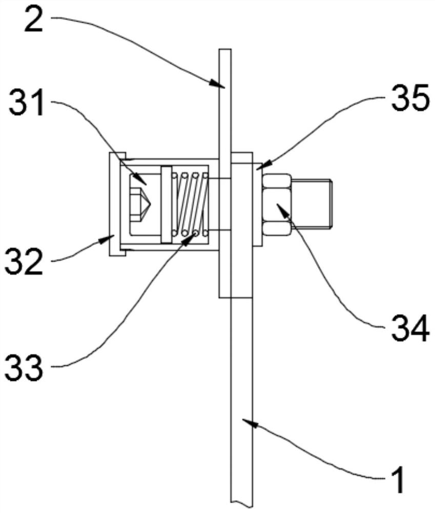
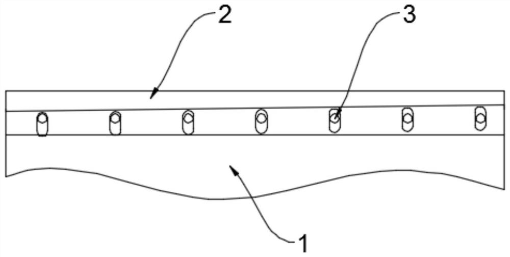
[0030] The embodiment of the present invention is realized like this, as figure 1 , image 3 A sealing device for an air preheater as shown, comprising:

[0031] Rotor bulkhead 1;

[0032] The sealing plate 2 is connected with the rotor compartment plate 1 through a plurality of soft fixing mechanisms 3, and slides relative to the rotor compartment plate 1 when the force on the sealing plate 2 exceeds a threshold value.

[0033] In the actual application of the present invention, the sealing plate 2 and the rotor compartment plate 1 are connected and fixed by setting the soft fixing mechanism 3, such as figure 1 As shown, in actual operation, the rotor compartment plate 1 is deformed after being heated, such as image 3 As shown, since the sealing plate 2 can slide relativ...


PUM


Abstract

The invention relates to a sealing device for an air preheater, and belongs to the technical field of preheaters. The sealing device comprises a rotor shifting board and a sealing plate, the sealing plate is connected with the rotor shifting board through a plurality of soft fixing mechanisms, and when the stress of the sealing plate exceeds a threshold value, the sealing plate slides relative to the rotor shifting board. The sealing plate does not slide relatively under the condition that the load is not changed, namely thermal deformation is not changed, and the sealing plate can be driven by a guide device to adjust the sealing position only under the condition that the load is changed and the thermal deformation is changed; a preset gap is kept between a seal and the reference for a long time, and the contact phenomenon, namely friction loss and friction energy consumption, does not exist; and the boiler efficiency can be improved, the output energy consumption of a primary fan and a secondary fan is reduced, the energy-saving significance is very important, the wind erosion damage of the internal structure of the air pre-heater can be greatly reduced, and the service life of the internal structure of the air pre-heater can be prolonged.

Description

technical field [0001] The invention relates to the technical field of preheaters, in particular to a sealing device for an air preheater. Background technique [0002] The air preheater is the heating surface where the flue gas in the flue at the tail of the boiler preheats the air before entering the boiler to a certain temperature through the internal cooling fins. It is a device used to improve the heat exchange performance of the boiler and reduce energy consumption. Air preheaters are generally divided into three types: plate type, rotary type and tube type. [0003] There are many relative rotating parts of the air preheater, all of which are static and dynamic seals and the working conditions are relatively harsh. The main air leakage areas include the following parts. Air leakage in the diameter direction between the hot primary air and the flue gas side, air leakage in the diameter direction between the hot secondary air and the flue gas, air leakage in the diamet...

Claims


Application Information

Patent Timeline
IPC IPC(8): F23L15/00F23J15/06F16J15/3268F16J15/3284
CPCF23L15/00F23J15/06F16J15/3284F16J15/3268Y02E20/34
Inventor 马强
Owner 马强
Why Eureka
Try Eureka