High-efficiency heat exchanger capable of realizing flue gas waste heat recovery

A flue gas waste heat and high-efficiency technology, applied to heat exchangers, heat exchanger types, heat exchanger shells, etc., can solve the problems of reducing heat exchange effect and efficiency, waste of resources, energy loss, etc., to improve the effect and Efficiency, the effect of reducing energy loss and waste

Active Publication Date: 2021-12-07
GUANGZHOU JIEMA HEAT EXCHANGE EQUIP
View PDF6 Cites 1 Cited by
  • Summary
  • Abstract
  • Description
  • Claims
  • Application Information

AI Technical Summary

Problems solved by technology

[0002] A heat exchanger is an energy-saving device that transfers heat between materials between two or more fluids at different temperatures. It transfers heat from a fluid with a higher temperature to a fluid with a lower temperature, so that the fluid temperature reaches the process The specified index is to meet the needs of process conditions, and it is also one of the main equipment to improve energy utilization. In industrial production, a large amount of smoke will be generated, and these smoke will be directly discharged into the air, which will cause air pollution. At the same time The heat contained in the flue gas will also cause waste of resources
[0003] In industrial production, due to different working conditions, the heat carried by the flue gas will be different, but the existing flue gas waste heat recovery high-efficiency heat exchanger cannot adjust the work of the heat exchanger in time according to the amount of heat carried by the flue gas Mode and water flow, thereby reducing the effect and efficiency of heat exchange, and causing a part of energy loss and waste, which is very inconvenient to use. Therefore, in view of the above situation, it is urgent to develop a high-efficiency heat exchanger for flue gas waste heat recovery to To overcome the deficiencies in the current practical application

Method used


Image

  • High-efficiency heat exchanger capable of realizing flue gas waste heat recovery
  • High-efficiency heat exchanger capable of realizing flue gas waste heat recovery
  • High-efficiency heat exchanger capable of realizing flue gas waste heat recovery

Examples


Embodiment Construction

[0021] The technical solutions in the embodiments of the present invention will be clearly and completely described below in conjunction with the accompanying drawings in the embodiments of the present invention. Obviously, the described embodiments are only some, not all, embodiments of the present invention. Based on the embodiments of the present invention, all other embodiments obtained by persons of ordinary skill in the art without creative efforts fall within the protection scope of the present invention.

[0022] The specific implementation of the present invention will be described in detail below in conjunction with specific embodiments.

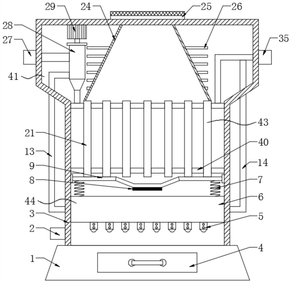
[0023] see Figure 1-6 , a high-efficiency flue gas waste heat recovery heat exchanger provided by an embodiment of the present invention includes a heat exchange box 3 and a support platform 1 for fixing the heat exchange box 3, and also includes:

[0024] A water delivery mechanism 41, the water delivery mechanism 41 is located ...


PUM


Abstract

The invention relates to the technical field of waste heat recovery, in particular to a high-efficiency heat exchanger capable of realizing flue gas waste heat recovery. The high-efficiency heat exchanger comprises a heat exchange box and a supporting platform used for fixing the heat exchange box and further comprises a water conveying mechanism and a smoke inlet mechanism; the water conveying mechanism is located on the heat exchange box; the water conveying mechanism comprises an adjusting assembly and a heat exchange assembly, the adjusting assembly comprises a flow adjusting pipe and an adjusting piece, the flow adjusting pipe is rotationally connected with the adjusting piece, and the heat exchange assembly comprises a heat exchange piece; the smoke inlet mechanism is connected with the heat exchange box and the water conveying mechanism; the smoke inlet mechanism comprises a blocking assembly and a control assembly, the control assembly comprises a flow dividing pipe and a control box, a lifting plate is installed in the control box in a sealed and sliding mode, and a sensitive piece is further installed in the control box. According to the high-efficiency heat exchanger capable of realizing flue gas waste heat recovery, heat in flue gas can be fully absorbed, the heat exchange effect and efficiency are improved, the energy loss and waste are reduced, and convenience is brought to a user.

Description

technical field [0001] The invention relates to the technical field of waste heat recovery, in particular to a high-efficiency heat exchanger for flue gas waste heat recovery. Background technique [0002] A heat exchanger is an energy-saving device that transfers heat between materials between two or more fluids at different temperatures. It transfers heat from a fluid with a higher temperature to a fluid with a lower temperature, so that the fluid temperature reaches the process The specified index is to meet the needs of process conditions, and it is also one of the main equipment to improve energy utilization. In industrial production, a large amount of smoke will be generated, and these smoke will be directly discharged into the air, which will cause air pollution. At the same time The heat contained in the flue gas will also cause waste of resources. [0003] In industrial production, due to different working conditions, the heat carried by the flue gas will be differ...

Claims


Application Information

Patent Timeline
Patent Type & Authority Applications(China)
IPC IPC(8): F28D21/00F28F27/00F28F9/22
CPCF28D21/0003F28F27/00F28F9/22Y02E20/30
Inventor 冯育周江广华陈飞勇谭融婷
Owner GUANGZHOU JIEMA HEAT EXCHANGE EQUIP
Why Eureka
Try Eureka