Oil smoke filtering device

A technology of oil fume filtration and filtering mechanism, which is applied in the direction of oil fume removal, dispersed particle filtration, household heating, etc. It can solve the problems of device clogging, running speed, device filtration efficiency reduction, slowing down, etc., to achieve enhanced vibration effect and increased suction range , the effect of improving work performance

Inactive Publication Date: 2021-12-10
高伟鹏
View PDF0 Cites 0 Cited by
  • Summary
  • Abstract
  • Description
  • Claims
  • Application Information

AI Technical Summary

Problems solved by technology

[0003] The oil fume filter devices currently on the market, when the oil fume sucked into the filter, the oil stains formed by the liquid oil adhere to the parts of the device when passing through the inside of the device, it is easy to cause the device to block or slow down the operation speed, thereby reducing the filtration efficiency of the device

Method used


Image

  • Oil smoke filtering device
  • Oil smoke filtering device
  • Oil smoke filtering device

Examples


Embodiment Construction

[0025] The following will clearly and completely describe the technical solutions in the embodiments of the present invention with reference to the accompanying drawings in the embodiments of the present invention. Obviously, the described embodiments are only some, not all, embodiments of the present invention.

[0026] Examples of the described embodiments are shown in the drawings, wherein like or similar reference numerals designate like or similar elements or elements having the same or similar functions throughout. The embodiments described below by referring to the figures are exemplary and are intended to explain the present invention and should not be construed as limiting the present invention.

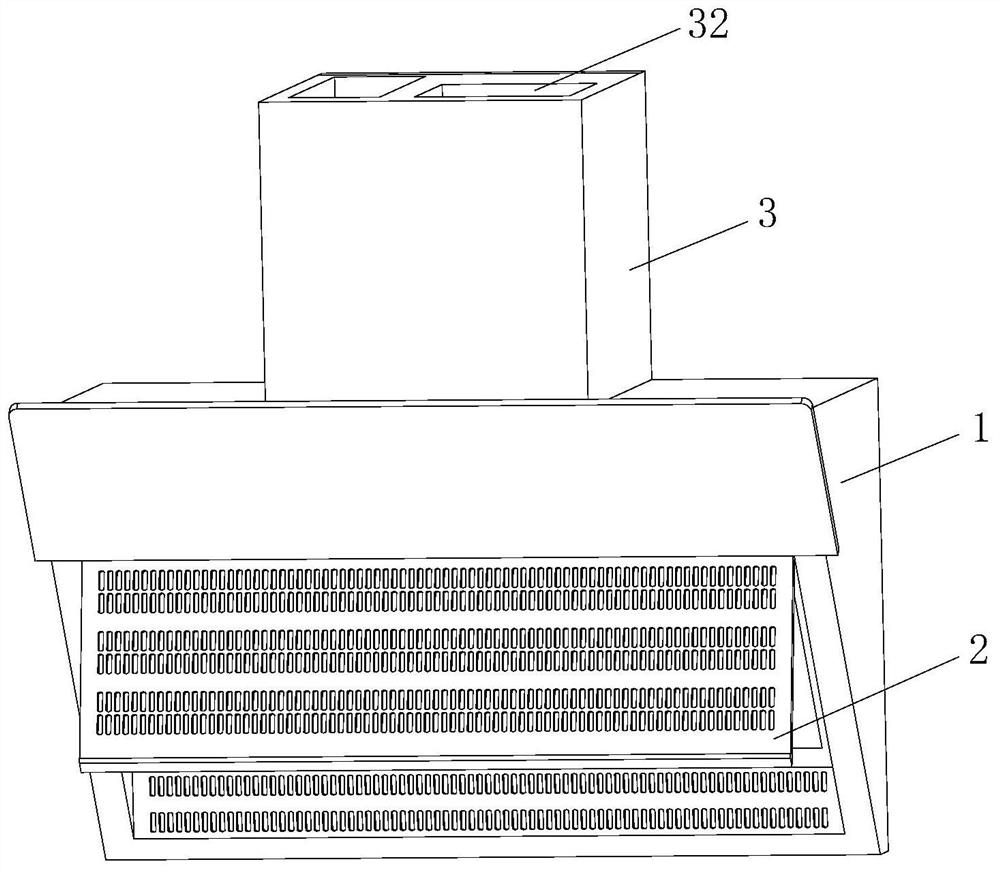
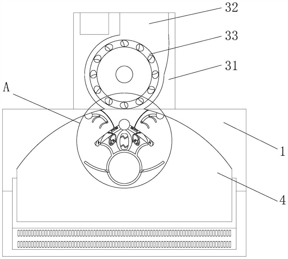
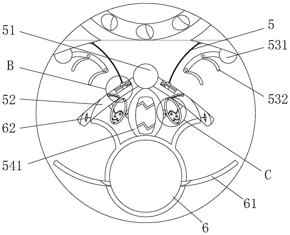
[0027] see Figure 1-7 , the present invention provides a technical solution: a lampblack filtering device, comprising a body 1, a smoke inlet plate 2 is installed on the front lower end of the body 1, a smoke exhaust mechanism 3 is fixedly installed on the top of the body 1...


PUM


Abstract

The invention discloses an oil smoke filtering device, and relates to the technical field of oil smoke filtering. The oil smoke filtering device comprises a machine body, a smoke inlet plate is rotationally installed at the lower end of the front face of the machine body, a smoke discharging mechanism is fixedly installed at the top of the machine body, a smoke inlet groove is formed in the inner side of the machine body, a filtering mechanism is fixedly installed in the center of the inner side of the smoke inlet groove, and an oil collecting bin is fixedly installed at the lower end of the filtering mechanism; a smoke exhaust mechanism comprises an exhaust pipeline, a smoke outlet and an exhaust fan, the exhaust pipeline is fixedly mounted at the top of the machine body, the smoke outlet is formed in the top of the exhaust pipeline, and the exhaust fan is rotationally mounted on the inner side of the exhaust pipeline. According to the oil smoke filtering device, when smoke exhaust mechanism works, the filtering mechanism is driven by airflow in the inner side of the device to operate, so that oil smoke at the bottom of the filter screen is shaken off into the oil collecting bin at the bottom, the dripping time of liquid oil is shortened, and the situation that the liquid oil forms oil stain accumulation on the surface of the filter screen, and consequently the filtering efficiency of the device is affected is avoided.

Description

technical field [0001] The invention relates to the technical field of oil fume filtering, in particular to an oil fume filtering device. Background technique [0002] The oil fume filter device is mainly used for the purification and treatment of low-altitude oil fumes in the kitchen. It is used in hotels, restaurants, restaurants, restaurants, schools, institutions, factories and other places. Food frying and cooking processing industries, oil splash heat treatment workshops, oil mist lubrication workshops , workpiece welding workshop and industrial occasions such as olefin oil boiler discharge; while the general oil fume filter device uses the rotation of the exhaust fan to drive the gas flow inside the device, so that the oil fume is sucked into the filter, and finally discharged through the upper exhaust port. [0003] The oil fume filter devices currently on the market, when the oil fume sucked into the filter, the oil stains formed by the liquid oil adhere to the part...

Claims


Application Information

Patent Timeline
Patent Type & Authority Applications(China)
IPC IPC(8): B01D46/10B01D46/00F24C15/20
CPCB01D46/10B01D46/0005F24C15/2035
Inventor 高伟鹏
Owner 高伟鹏
Why Eureka
Try Eureka