Structured light interference velocimeter

A structured light and velocimeter technology, applied in the field of optical measurement, can solve the problems of unable to measure the translational motion information of the target object, unable to measure the rotational motion information of the target object, unable to achieve one-time non-contact simultaneous measurement, etc., to increase the distance range, The effect that is conducive to production and production

Inactive Publication Date: 2021-12-10
HUAZHONG UNIV OF SCI & TECH
View PDF3 Cites 0 Cited by
  • Summary
  • Abstract
  • Description
  • Claims
  • Application Information

AI Technical Summary

Problems solved by technology

[0002] The traditional laser interferometer based on the classical Doppler effect can use the laser Gaussian beam to measure the translational motion information of the target object, such as non-contact measurement of the horizontal displacement and linear velocity of the target object, but it cannot measure the target object’s Rotary motion information
At present, the method of obtaining the rotational motion information of the target object generally adopts contact or mechanical measurement, such as an angular velocity sensor based on a gyroscope design, or an angular velocity measuring instrument based on a mechanical gear, but these methods cannot measure the translational motion information of the target object
For compound motions that contain both translational motion information and rotational motion information, such as spiral motion, the one-time non-contact simultaneous measurement of both translational and rotational motions cannot be achieved through existing methods
At present, there is no effective method to realize real-time tracking of the trajectory and form of the target object with complex motion. In view of this, it is extremely necessary to design a device for real-time monitoring of compound motion.

Method used


Image

  • Structured light interference velocimeter
  • Structured light interference velocimeter
  • Structured light interference velocimeter

Examples


specific Embodiment approach

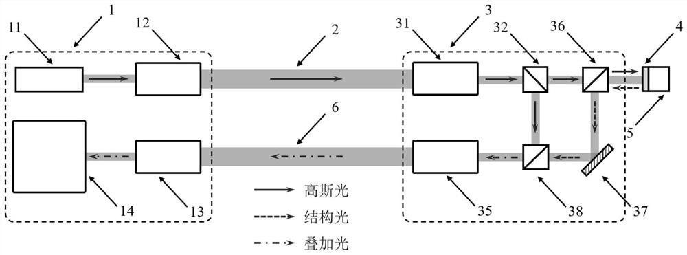
[0040] like figure 2 As shown, an improvement of a structured light interference velocimeter provided by the present invention, the specific implementation method is as follows:

[0041] The device includes: a transmitting device 1, a receiving device 3, and a reflective compound spiral phase plate 4; wherein, the transmitting device 1 includes a laser 11, a first beam expander 12, a first beam reducer 13, and a dual position detection device 14; The device 3 includes a second beam reducer 31 , a first beam splitter 32 , a second beam splitter 36 , a third mirror 37 , a third beam splitter 38 , and a second beam expander 35 . The free-space Gaussian light output by the laser 11 is sent to the receiving device 3 along the transmitting optical path 2 after the beam size is adjusted by the first beam expander 12; the second beam reducer 31 receives the Gaussian light transmitted by the transmitting device 1 and reduces the beam size , the first beam splitter 32 divides the Gaus...


PUM


Abstract

The invention discloses a structured light interference velocimeter which comprises transmitting equipment, receiving equipment and a reflective composite spiral phase plate. The transmitting equipment is arranged in a measurement site and used for transmitting, receiving and processing optical signals. The receiving equipment is arranged at a remote object to be measured and used for detecting and reversely transmitting the optical signals, and the receiving equipment can adopt Michelson or Mach-Zehnder interference configuration. A beam expander and a beam compressor are adopted in the transmitting equipment and the receiving equipment to adjust the size of a light beam, and collimation transmission of a light field between a near end and a far end is ensured. The reflective composite spiral phase plate is adhered to the surface of an object to be measured and converts irradiated detection light into structured light. Reference Gaussian light and the structured light are combined into superposed light, and the superposed light is detected and subjected to signal processing by using a double-position detection device in the transmitting equipment, so that multi-dimensional movement speed information of translation, rotation or combination of translation and rotation of the remote object to be measured can be obtained. The structured light interference velocimeter has a wide application prospect in the aspects of optical measurement, sensing and the like, and fills the blank in the related technical field.

Description

technical field [0001] The invention belongs to the field of optical measurement, and more specifically relates to a structured light interference velocimeter. Background technique [0002] The traditional laser interferometer based on the classic Doppler effect can use the laser Gaussian beam to measure the translational motion information of the target object, such as the non-contact measurement of the horizontal displacement and linear velocity of the target object, but it cannot measure the target object’s Rotary motion information. At present, the method of obtaining the rotational motion information of the target object generally adopts contact or mechanical measurement, such as an angular velocity sensor based on a gyroscope design, or an angular velocity measuring instrument based on a mechanical gear, but these methods cannot measure the translational motion information of the target object . For compound motions that contain both translational motion information ...

Claims


Application Information

Patent Timeline
Patent Type & Authority Applications(China)
IPC IPC(8): G01P3/36
CPCG01P3/36
Inventor 王健万镇宇方良汤子毅
Owner HUAZHONG UNIV OF SCI & TECH
Why Eureka
Try Eureka