
High-voltage direct-current charging circuit and method for electric vehicle

A charging circuit and electric vehicle technology, applied in electric vehicle charging technology, electric vehicles, battery circuit devices, etc., can solve the problems of insufficient infrastructure construction of DC fast charging piles, and achieve the requirements of increasing inductance, reducing capacitance, The effect of protecting the mechanical system

Pending Publication Date: 2021-12-10
LEADRIVE TECH (SHANGHAI) CO LTD
View PDF0 Cites 1 Cited by
  • Summary
  • Abstract
  • Description
  • Claims
  • Application Information

AI Technical Summary

Problems solved by technology

Therefore, on the electric vehicle side, more and more cases are equipped with 800V high-voltage busbar systems, but the infrastructure construction of DC fast charging piles compatible with 800V battery systems is insufficient

Method used


Image

  • High-voltage direct-current charging circuit and method for electric vehicle
  • High-voltage direct-current charging circuit and method for electric vehicle
  • High-voltage direct-current charging circuit and method for electric vehicle

Examples


Embodiment Construction

[0046] The advantages of the present invention will be further elaborated below in conjunction with the accompanying drawings and specific embodiments.

[0047] Reference will now be made in detail to the exemplary embodiments, examples of which are illustrated in the accompanying drawings. When the following description refers to the accompanying drawings, the same numerals in different drawings refer to the same or similar elements unless otherwise indicated. The implementations described in the following exemplary examples do not represent all implementations consistent with the present disclosure. Rather, they are merely examples of apparatuses and methods consistent with aspects of the present disclosure as recited in the appended claims.

[0048] The terminology used in the present disclosure is for the purpose of describing particular embodiments only, and is not intended to limit the present disclosure. As used in this disclosure and the appended claims, the singular...


PUM


Abstract

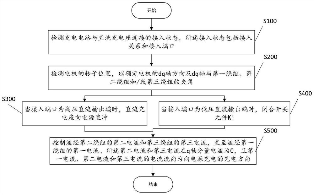
The invention provides a high-voltage direct-current charging circuit and method for an electric vehicle. The charging circuit comprises a power supply; a motor controller which comprises a first phase, a second phase and a third phase; a motor which comprises a first winding, a second winding and a third winding; a switch element K1 in which one end of is connected between the first winding and the first phase in parallel, and the other end is externally connected to a direct current charging seat; and an interface capacitor C2 in which one end is connected with the switch element K1, and the other end of the interface capacitor C2 is connected to the charging circuit. When a direct-current charging seat outputs low-voltage direct current to the charging circuit, the switching element K1 is closed, the first phase is disconnected, and the second phase and the third phase are closed, so that the second phase and the third phase serve as switching bridge arms of a booster circuit of the charging circuit, and the low-voltage direct current is boosted to high-voltage direct current. After the technical scheme is adopted, a driving inverter is used as a DC-DC circuit of the power conversion circuit, so that the 400V direct-current quick charging pile can be directly applied to direct-current quick charging of an electric automobile with an 800V high-voltage bus system.

Description

technical field [0001] The invention relates to the field of electric vehicles, in particular to a high-voltage DC charging circuit and a charging method for an electric vehicle. Background technique [0002] With the rapid development of electric vehicles, the main problems that should be solved are the cruising range and charging speed of users. When the power of the electric vehicle is exhausted, the user needs to charge it quickly to continue driving. [0003] The usual way of charging is AC charging or DC charging. Due to the fast charging speed of DC charging, a large number of DC charging base stations have been built. For electric vehicles with a 400V power supply system that has been popularized at present, a relatively complete infrastructure has been built. Compared with the 400V DC bus system, the electric vehicle with 800V DC bus system has more advantages in power performance. Therefore, on the electric vehicle side, more and more cases are equipped with 800...

Claims


Application Information

Patent Timeline
Patent Type & Authority Applications(China)
IPC IPC(8): H02J7/00B60L53/14B60L53/24B60L53/10
CPCH02J7/00H02J7/0013B60L53/14B60L53/11B60L53/24Y02T10/70Y02T10/72Y02T10/92Y02T10/7072Y02T90/14
Inventor 沈捷李一粟
Owner LEADRIVE TECH (SHANGHAI) CO LTD
Learn More