Automatic double-lifting coil stock uncoiler

An uncoiler and coil material technology, which is applied in the field of automatic double-lifting coil uncoiler, can solve the problems of the uncoiler plate deviates from the coil track, cannot be accurately uncoiled, and the coil edge is not neat, and achieves reduced diameter requirements and automation. The effect of high degree and equipment cost reduction

Pending Publication Date: 2021-12-14
安徽东海裕祥智能装备科技有限公司
View PDF0 Cites 0 Cited by
  • Summary
  • Abstract
  • Description
  • Claims
  • Application Information

AI Technical Summary

Problems solved by technology

[0003] The current uncoiler reel shaft is one-sided cantilever type, and the loading is hoisted by crane, which has low operation efficiency; when the coil material is sleeved on the reel shaft, the reel shaft needs a high bending moment resistance. First of all, for The installation bearing of the reel shaft and the diameter of the reel shaft put forward higher requirements, and the equipment cost is high; secondly, when feeding, it is necessary to align the central axis of the reel with the central axis of the reel shaft, otherwise the reel The tension force of the tensioning mechanism installed on the outer side of the drum shaft i

Method used


Image

  • Automatic double-lifting coil stock uncoiler
  • Automatic double-lifting coil stock uncoiler
  • Automatic double-lifting coil stock uncoiler

Examples


Embodiment 1

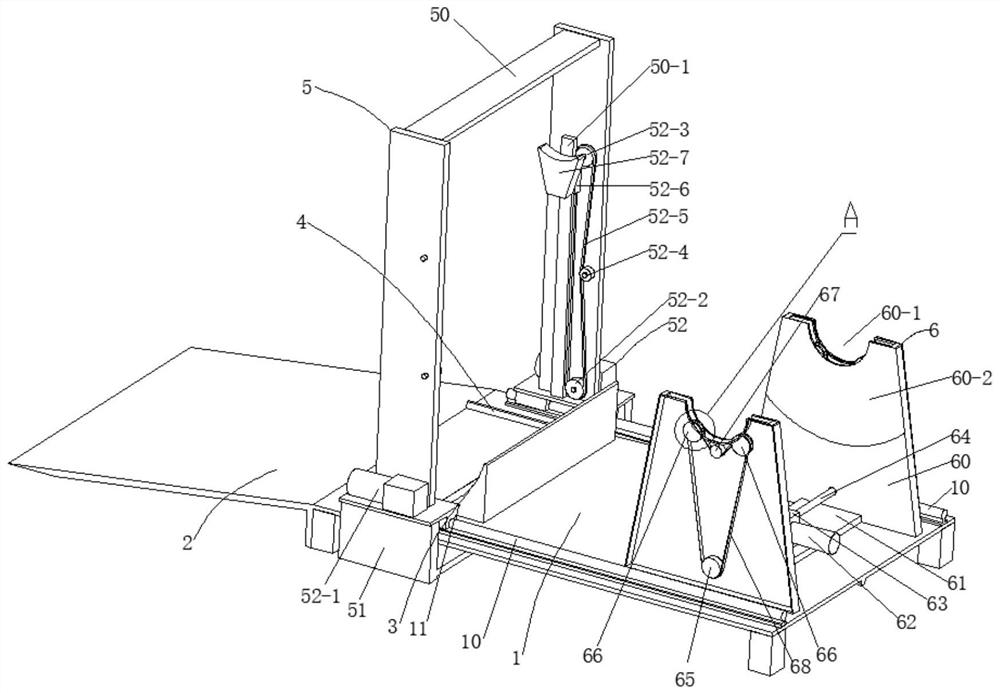
[0043] In the automatic double-lifting coil uncoiler of the present invention, first keep the lifting fork 52-7 in the lifting device 52 at a low position, then hoist the coil or forklift the fork on the cart, and pass the cart loaded with coil The inclined table 2 is pushed onto the base platform 1, and then the coil material is pushed down, so that the coil material is positioned by the arc positioning plate 3 in the front and rear direction, and positioned by the horizontal positioning bar 4 in the left and right direction.

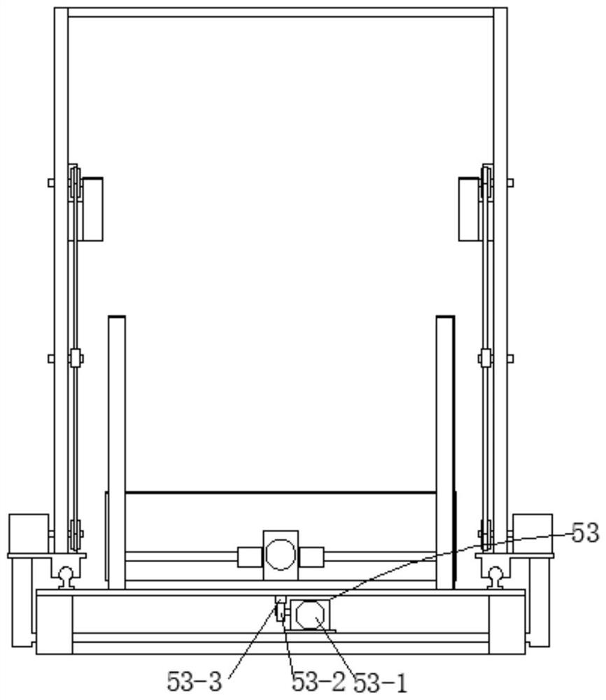
[0044] Then, start the servo motor one 52-1 in the lifting device 52, the servo motor one 52-1 drives the chain 52-5 to move upwards with the slide block 52-6 through the drive sprocket 52-2, and the slide block 52-6 moves upwards with the slide block 52-6. Lifting fork 52-7 moves upwards, then lifting fork 52-7 contacts with the two ends of the shaft inserted into the coil material center, and then coil material continues to move upwards with lifting f...

Embodiment 2

[0052] On the basis of Embodiment 1, the top of the bracket 60 is provided with a groove 60-1 to ensure the safety of the coil material falling; the inside of the bracket 60 is provided with a positioning slide 60-2, so that the coil material board is uncoiled When aligning the left and right positions and positioning, the wear resistance of the bracket 60 is improved at the same time.

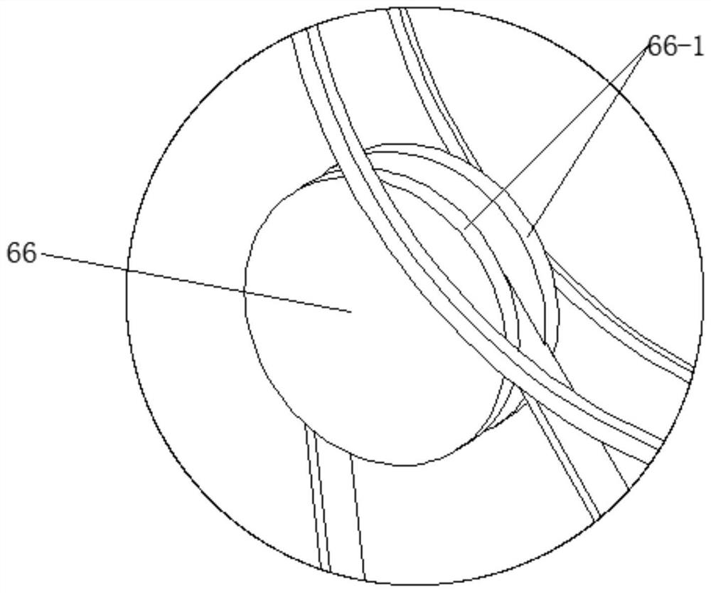
[0053] The two passive synchronous pulleys 66 are I-shaped wheels, and the outer circular surface of the passive synchronous pulley 66 is provided with a knurling structure 66-1, and the outer circular surface exceeds the groove 60-1, ensuring that the two passive synchronous pulleys Timing pulley 66 drive stability.


PUM


Abstract

The invention discloses an automatic double-lifting coil stock uncoiler. The automatic double-lifting coil stock uncoiler comprises a base platform, an inclined table, an arc positioning plate, a transverse positioning strip, a feeding device and an uncoiling device, wherein the inclined table is connected with the front end of the base platform in a spliced mode, and the arc positioning plate and the transverse positioning strip are connected with the upper end of the base platform in a fastened mode; and the feeding device is connected with the upper face of the front end of the base platform in a fastened mode, the uncoiling device is connected with the upper face of the rear end of the base platform in a fastened mode, and the whole coil stock feeding process is high in automation degree and operation efficiency. A drum shaft does not need very high bending moment resistance, so that the requirements on a mounting bearing of the drum shaft and the diameter of the drum shaft are reduced, and the equipment cost is reduced; precise uncoiling operation is achieved through the uncoiling device; and the phenomenon that an outer layer plate of a coil stock is centrifuged in the uncoiling process is avoided, the phenomenon that the edge of the coil stock is irregular due to outward deviation is avoided, and the phenomenon that the uncoiling plate deviates from the uncoiling track to cause the uncoiler to be stuck is also avoided.

Description

technical field [0001] The invention belongs to the technical field of uncoilers, in particular, the invention relates to an automatic double-lifting coil uncoiler. Background technique [0002] The uncoiler is a special equipment for metal plate leveling. The body is a welded box structure. The frequency conversion speed regulation motor drives the reel shaft to provide the main power for the uncoiler after being decelerated by the gearbox. [0003] The current uncoiler reel shaft is one-sided cantilever type, and the loading is hoisted by crane, which has low operation efficiency; when the coil material is sleeved on the reel shaft, the reel shaft needs a high resistance to bending moments. First of all, for The installation bearing of the reel shaft and the diameter of the reel shaft put forward higher requirements, and the equipment cost is high; secondly, when feeding, it is necessary to align the central axis of the reel with the central axis of the reel shaft, otherwi...

Claims


Application Information

Patent Timeline
IPC IPC(8): B21C47/22B21C47/28B21C47/34
CPCB21C47/22B21C47/28B21C47/34
Inventor 孙绵玉石贤林孙绵祥李雪鹏李红
Owner 安徽东海裕祥智能装备科技有限公司
Why Eureka
Try Eureka