Push-down emergency braking device and braking method for new energy vehicles
A new energy vehicle and emergency braking technology, applied in the field of new energy vehicle braking, can solve the problems of shortening the service life of the motor and poor braking performance, and achieve the effects of increasing the service life, avoiding wear and tear, and avoiding serious heat generation
- Summary
- Abstract
- Description
- Claims
- Application Information
AI Technical Summary
Problems solved by technology
Method used
Image

Examples
Embodiment 1
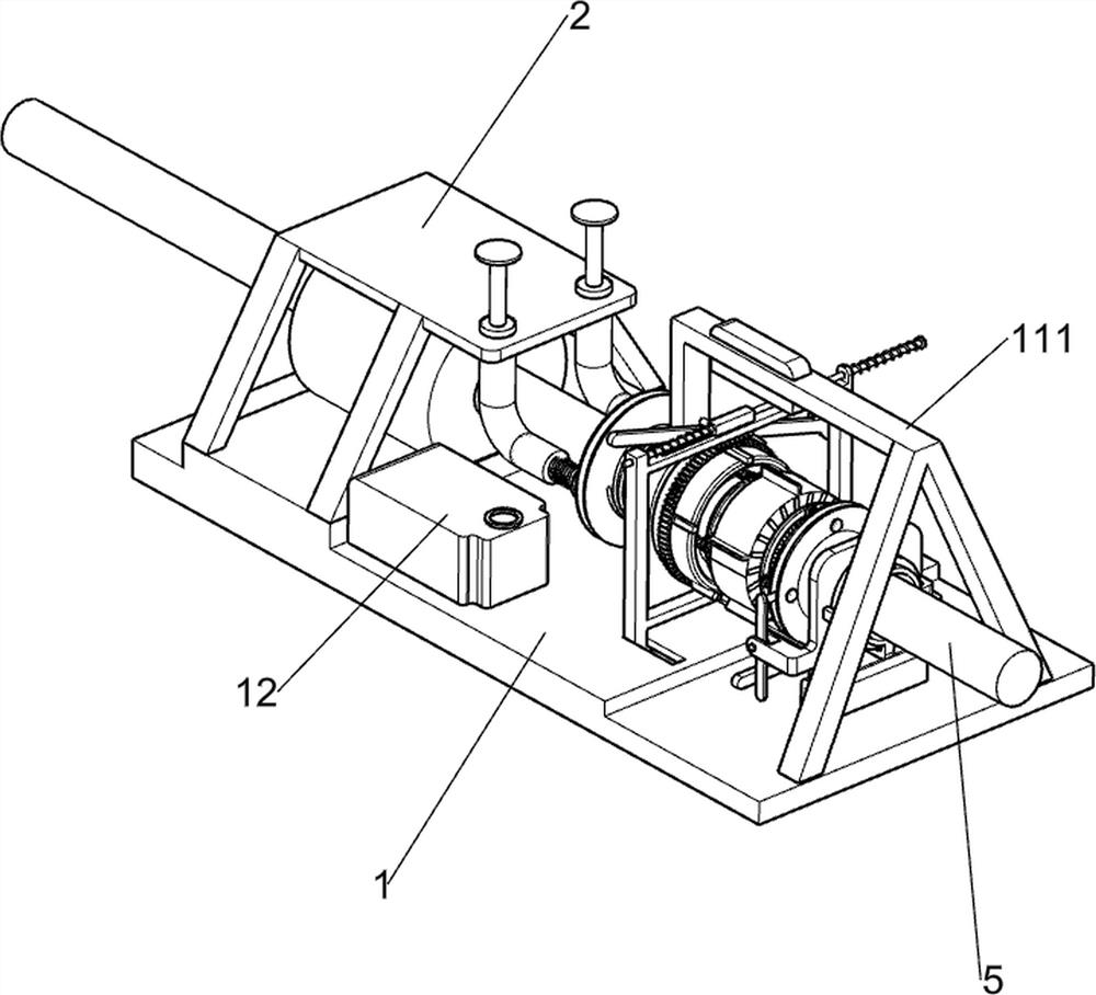
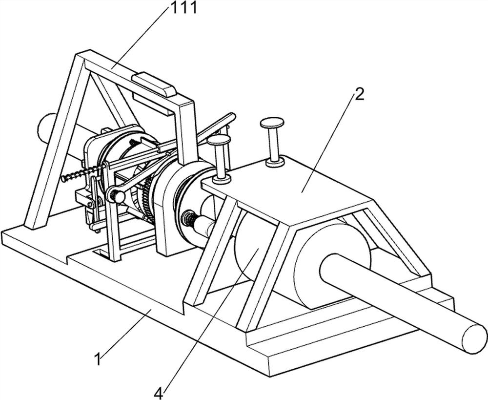
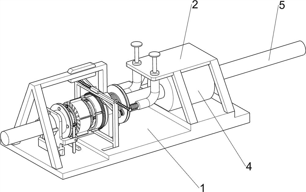
[0045] Push-down emergency braking device and braking method for new energy vehicles, such as figure 1 , figure 2 , image 3 , Figure 4 , Figure 5 , Figure 6 , Figure 7 , Figure 8 , Figure 9 , Figure 10 , Figure 11 , Figure 12 , Figure 13 , Figure 14 , Figure 15 and Figure 16 As shown, it includes a bottom plate 1, a motor top plate 2, a mounting plate 3, a servo motor 4, a rotating shaft 5, a fixed turntable 6, a primary side friction deceleration assembly 7, a secondary side friction deceleration assembly 8 and a rack brake assembly 9 The motor top plate 2 is fixedly installed on the rear side of the top surface of the bottom plate 1, the mounting plate 3 is fixedly installed on the middle part of the bottom plate 1, and the servo motor 4 for driving is fixedly installed on the rear side of the top surface of the bottom plate 1. The servo motor 4 is located below the motor top plate 2. The inside of the motor 4 is provided with a rotating shaft 5,...
Embodiment 2
[0053] On the basis of Example 1, such as Figure 14 As shown, it also includes a caliper stop assembly 10, the rear side of the moving frame 93 is provided with a caliper stop assembly 10, the caliper stop assembly 10 is used to block the sliding friction disc 75, and the caliper stop assembly 10 includes a fixed bolt 101 , movable calipers 102, torsion spring two 103 and brake pads 104, the movable frame 93 rear sides are fixedly connected with fixed bolts 101, the movable calipers 102 are connected with the movable calipers on the fixed bolts 101, and the torsion force is connected between the movable calipers 102 and the fixed bolts 101. Spring two 103, brake pad 104 is arranged in the middle part of movable caliper 102, and sliding rack block 94 is used for pushing movable caliper 102 and brake pad 104 to swing downward, and brake pad 104 is in contact with sliding friction disc 75, and brake pad 104 is used for sliding Friction disc 75 applies pressure.
[0054] When th...
Embodiment 3
[0056] On the basis of Example 2, such as figure 1 , figure 2 and Figure 15 As shown, it also includes an air-cooled heat dissipation assembly 11. The air-cooled heat dissipation assembly 11 is arranged on the front side of the top of the bottom plate 1. The air-cooled heat dissipation assembly 11 is used to dissipate heat to the parts. The air-cooled heat dissipation assembly 11 includes a cooling frame 111 and a wind Cooling port 112, bottom plate 1 top front side is fixedly installed with cooling rack 111, and cooling rack 111 is fixedly connected with mounting plate 3, and cooling rack 111 is provided with air-cooling port 112, and air-cooling port 112 is used for discharging cold wind.
[0057] During the braking and stopping process, high temperature will be generated between the components. The vehicle control system controls the cooling frame 111 to start, and blows cold air from the air cooling port 112. The cold air can take away the heat from each component to ac...
PUM
 Abstract
Description
Claims
Application Information
 - R&D
- Intellectual Property
- Life Sciences
- Materials
- Tech Scout
- Unparalleled Data Quality
- Higher Quality Content
- 60% Fewer Hallucinations
Browse by: Latest US Patents, China's latest patents, Technical Efficacy Thesaurus, Application Domain, Technology Topic, Popular Technical Reports.
© 2025 PatSnap. All rights reserved.Legal|Privacy policy|Modern Slavery Act Transparency Statement|Sitemap|About US| Contact US: help@patsnap.com