Automatic gear shifting actuator for new energy automobile

A new energy vehicle, automatic gear shifting technology, applied in transmission elements, vehicle parts, vehicle gearboxes, etc., can solve the problems affecting the safety performance of automatic gear shifting, gears are easy to wear, etc., to achieve low wear, smooth gas flow, Fast reset effect

Inactive Publication Date: 2021-12-14
杭州优协科技有限公司
View PDF8 Cites 0 Cited by
  • Summary
  • Abstract
  • Description
  • Claims
  • Application Information

AI Technical Summary

Problems solved by technology

In the automatic shifting actuator for vehicles, gears and other components are usually used for transmission. During the shifting operation, the gears are easily worn, which in turn affects the safety performance of automatic shifting.

Method used


Image

  • Automatic gear shifting actuator for new energy automobile
  • Automatic gear shifting actuator for new energy automobile
  • Automatic gear shifting actuator for new energy automobile

Examples


Embodiment 1

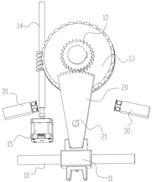
[0048] Figure 1~Figure 4 Schematically shows an automatic shift actuator for a new energy vehicle according to an embodiment of the present invention, including a shift lever 10, the shift lever 10 is connected to a sector gear 20, and the sector gear 20 is far away from the shift lever One end of 10 meshes with the main gear 12, and the reciprocating rotation of the main gear 12 drives the sector gear 20 to swing back and forth within a certain range, thereby realizing the movement of the shift lever 10.

[0049] like figure 1 As shown, the shift lever 10 is arranged horizontally, the middle part is covered with a connecting piece 11 , and the end of the sector gear 20 away from the main gear 12 is fixedly connected with the connecting piece 11 . The outer side of the main gear 12 is provided with a coaxial worm wheel 13 , the worm wheel 13 meshes with the worm 14 , and one end of the worm 14 is connected with the output end of the drive motor 15 . The worm 14 drives the w...

Embodiment 2

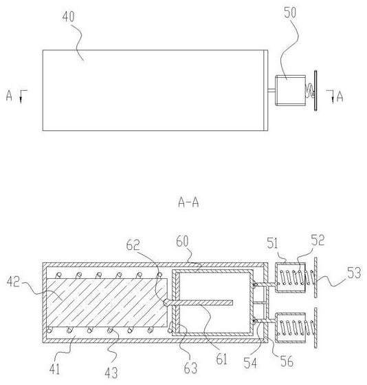
[0062] Figure 5~Figure 8 Schematically shows an automatic shift actuator for new energy vehicles according to another embodiment of the present invention, the difference from Example 1 is:

[0063] One end of the third base body 60 away from the spherical connection portion 62 is configured with a first rebound support member 64 and a second rebound support member 65, the first rebound support member 64 is located inside the third base body 60, and is connected to the swing rod 61 The end of the third base body 60 is matched with the second resilient support member 65 outside the third base body 60 and fits with the end of the third base body 60 .

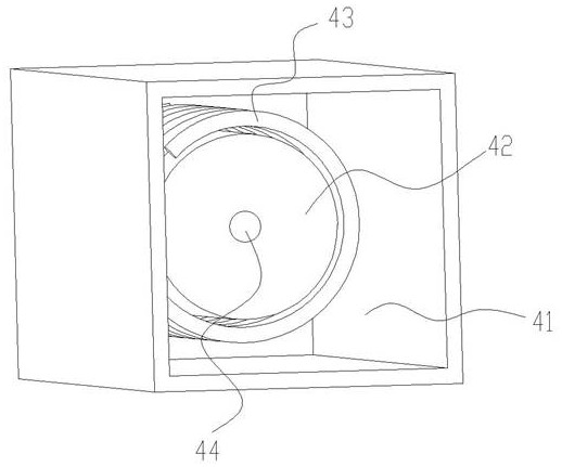
[0064] The first resilient support member 64 has the same structure as the second resilient support member 65, including a support circular plate 66 and a plurality of support feet 67, and the plurality of support feet 67 are evenly distributed on the edge of the support circular plate 66 in a radial shape, like Image 6 As show...


PUM


Abstract

The invention discloses an automatic gear shifting actuator for a new energy automobile. The automatic gear shifting actuator comprises a gear shifting driving lever, the gear shifting driving lever is connected with a sector gear, the end, away from the gear shifting driving lever, of the sector gear is engaged with a main gear, a worm gear coaxial with the main gear is arranged on the outer side of the main gear, and the main gear and the worm gear rotate synchronously; the worm gear is engaged with a worm, and one end of the worm is connected with the output end of a driving motor; an angle sensor is arranged above the worm gear and used for monitoring the rotation angle of the worm gear; the driving motor and the angle sensor are electrically connected with an external electric control unit; and reset assemblies are symmetrically arranged on the two sides of the sector gear and arranged at the limit swing position of the sector gear. The automatic gear shifting actuator is compact in structure, stable in transmission, capable of rapidly achieving resetting, low in wear degree and high in stability, and has the advantages of being small in vibration impact, low in noise, rapid in heat dissipation and the like in the automatic gear shifting process.

Description

technical field [0001] The invention belongs to the technical field of automatic operation of new energy vehicles, and in particular relates to an automatic shift actuator for new energy vehicles. Background technique [0002] Automotive electronically controlled mechanical automatic transmission AMT is based on manual transmission and dry clutch, applying electronic technology and automatic transmission theory, with electronic control unit ECU as the core, and controlling the separation and engagement of the clutch through hydraulic or pneumatic actuators. The gear selection and shifting operation and the adjustment of the engine throttle realize the automatic operation of starting and shifting. In the automatic shifting actuator for vehicles, gears and other components are usually used for transmission, and the gears are easily worn during the shifting operation, which in turn affects the safety performance of the automatic shifting. [0003] The utility model patent with...

Claims


Application Information

Patent Timeline
IPC IPC(8): F16H61/32F16H63/30F16H57/04
CPCF16H61/32F16H63/304F16H57/0006F16H57/0416F16H2061/2892F16H2200/0021F16H2063/3066F16H2063/3089
Inventor 张涛
Owner 杭州优协科技有限公司
Why Eureka
Try Eureka