System, method and device for performing pulse energy control on optical fiber amplifier, processor and computer readable storage medium thereof

A fiber amplifier and pulse energy technology, applied in lasers, transmission systems, laser components, etc., can solve problems such as no good fiber amplifiers can be used, low duty cycle, and inability to accurately detect output power, etc., to achieve outstanding applications effect, improved pulse stability, and reduced work preparation time

Inactive Publication Date: 2021-12-14
上海拜安实业有限公司
View PDF0 Cites 1 Cited by
  • Summary
  • Abstract
  • Description
  • Claims
  • Application Information

AI Technical Summary

Problems solved by technology

Due to the narrow pulse width and low duty cycle of this type of signal, the conventional method cannot accurately detect the output power and cannot realize the APC mode, so it has been more helpless to use the ACC mode to control
[0017]ACC mode can only realize the amplification of the amplifier, but in use, due to the change of input power, the change of ambient temperature, the

Method used


Image

  • System, method and device for performing pulse energy control on optical fiber amplifier, processor and computer readable storage medium thereof
  • System, method and device for performing pulse energy control on optical fiber amplifier, processor and computer readable storage medium thereof
  • System, method and device for performing pulse energy control on optical fiber amplifier, processor and computer readable storage medium thereof

Examples


Embodiment approach

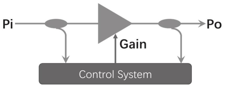
[0061] As a preferred embodiment of the present invention, the system includes the following processes:

[0062] (a) The energy detection module judges whether the currently detected output pulse energy is lower than the system preset light pulse energy value, if so, enters the processing process (2), otherwise, enters the processing process (3);

[0063] (b) The control detection subsystem automatically increases the amplifier gain of the optical fiber amplification module until the output pulse energy is equal to the system preset optical pulse energy value, and enters the processing process (4);

[0064] (c) The control detection subsystem automatically reduces the amplifier gain of the optical fiber amplification module until the output pulse energy is equal to the system preset optical pulse energy value, and enters the processing process (4);

[0065] (d) The output pulse energy is constant, and the constant output control of the optical fiber amplifier is completed.

...


PUM


Abstract

The invention relates to a pulse energy control system for an optical fiber amplifier, and the system comprises an input optical coupler which is used for inputting an input optical pulse signal into the system for energy detection; an optical fiber amplification module which is used for performing signal amplification processing on the input optical pulse signal; an output optical coupler which is used for carrying out shunt processing on the amplified input optical pulse signal; an energy detection module which is used for detecting output pulse energy of the output optical pulse signal; and a control detection subsystem which is used for carrying out real-time adjustment of gain control according to the input detection and energy detection results of the optical fiber signals. The invention further relates to a corresponding method and device, a processor and a storage medium thereof. By adopting the system, the method, the device, the processor and the storage medium of the invention, the pulse output stabilization time is shortened to minutes, the process is not influenced by environmental changes, the work preparation time of the system is shortened by hundreds of times, and the pulse stability of the system is improved by dozens of times.

Description

technical field [0001] The present invention relates to the technical field of photoelectric signal processing, in particular to the technical field of control modes of optical fiber amplifiers, and specifically refers to a system, method, device, processor and computer-readable storage medium for pulse energy control of optical fiber amplifiers. Background technique [0002] The usual fiber amplifier EDFA / YDFA generally has three control modes: [0003] 1. Automatic power control mode (APC) [0004] APC: Auto Power Control, automatic power control or constant power mode, means that no matter how the input power Pi changes, this mode adjusts the gain of the amplifier in real time by detecting the output power Po to ensure that the output power Po is constant. Such as figure 1 As shown, Po=Pi+Gain. [0005] For example, when the input power Pi decreases due to line attenuation or system aging, and the control system detects that Po decreases, the system will automatically ...

Claims


Application Information

Patent Timeline
IPC IPC(8): H01S3/067H01S3/13H04B10/293
CPCH01S3/06754H01S3/1305H04B10/293H04B10/2931
Inventor 张涛陈锋华
Owner 上海拜安实业有限公司
Why Eureka
Try Eureka