Quick-release backwash filter

A backwashing and filter technology, applied in fixed filter element filters, filtration separation, chemical instruments and methods, etc., can solve the problems of instrument blockage and damage, filter screen cannot be cleaned, secondary pollution of formation, etc., and achieve excellent impact resistance. performance, improve installation convenience, and improve the effect of installation stability

Inactive Publication Date: 2021-12-17
西安恒利石油设备有限公司
View PDF3 Cites 0 Cited by
  • Summary
  • Abstract
  • Description
  • Claims
  • Application Information

AI Technical Summary

Problems solved by technology

After centralized treatment, the oilfield sewage is transported to the water injection wellhead through pipelines over a long distance. Due to the drop in temperature, the growth of bacteria and the secondary pollution of the pipeline, the water quality at the wellhead has deteriorated significantly, which is far from meeting the requirements for reinjection water in the formation. filter again
During the high-pressure water injection process, the residues in the reinjection water, such as scale, rust, and some suspended solids, not only cause secondary pollution to the formation, but also cause blockage and damage to flow meters, pressure transmitters and other instruments in the water injection system , which seriously affects the normal operation of the equipment
Although the previous wellhead high-pressure filter has a certain filtering effect on coarse particles, under high pressure, the filtering effect is not good. The impurities are adsorbed on the filter element, and the filter element is not enough to flush through the pressure difference on both sides of the filter element. At the same time, it is inconvenient to maintain and disassemble the filter element. Therefore, we propose a quick-release backwash filter

Method used


Image

  • Quick-release backwash filter
  • Quick-release backwash filter
  • Quick-release backwash filter

Examples


Embodiment Construction

[0023] Next, the technical solutions in the embodiments of the present invention will be described in connection with the drawings of the embodiments of the present invention, and it is understood that the described embodiments are merely the embodiments of the present invention, not all of the embodiments. Based on the embodiments of the present invention, all other embodiments obtained by those of ordinary skill in the art are in the range of the present invention without making creative labor premise.

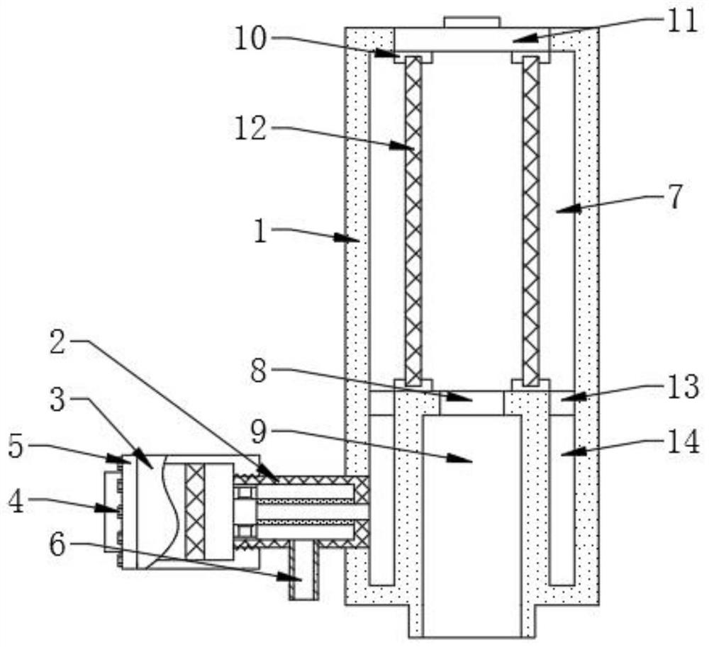
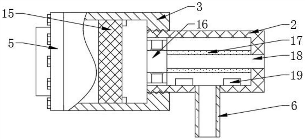
[0024] See figure 1 and figure 2 The present invention provides a technical solution: a quick-release anti-pressure washing filter, including the filter body 1, and the bottom of the filter body 1 is fixedly assembled with the anti-roller 2, and the two sets of anti-scrubbing 2 The outer ends are screwed to fit the filter cartridge 3, and the outer end of the two sets of filter cartridges 3 is fixedly assembled by the fastening screw 4, and the bottom end of the two groups of an...


PUM


Abstract

The invention discloses a quick-release backwash filter in the technical field of backwash filters. A protective cover is assembled on the top of the filter body in a threaded connection mode. Mounting bases are fixedly arranged at the bottom of the protective cover, and a secondary filter element is assembled between the two mounting bases in a clamped connection mode. A guide-in channel formed in the bottom of a filter bin is arranged on the outer side of the mounting base on the lower side. A water inlet bin is communicated with backwash cylinders. Filter screens are assembled in two filter cylinders. Primary filter elements communicated with the water inlet bin are fixedly assembled in the two backwash cylinders. Fluid directors arranged in the inner cavities of the backwash cylinders are fixedly assembled at the outer ends of the primary filter elements. Ultrasonic transducers arranged on the left side and the right side of a backwash water outlet pipe are fixed at the bottoms of the inner cavities of the two backwash cylinders. The secondary filter element can be quickly mounted, and can be conveniently maintained and replaced in the later period. The backwash effect can be improved, multi-stage filtration of water can be completed, and the filtration effect is improved.

Description

Technical field [0001] The present invention relates to the technical field of backwashing filters, and in particular a fast-release anti-scrub filter. Background technique [0002] Current oil well mining generally adopted: "Oil and gas water mixing → ground separation → sewage treatment → return" oilfield sewage treatment retardation process technology. After the water field is concentrated, the pipe is transported to the injection wellhead. Due to the low temperature reduction, the secondary pollution of bacteria and the secondary pollution of the pipeline, the wellhead is greatly deteriorated, far from being able to meet the surface return water requirements, therefore needs to return water to the wellhead Filter again. During the high pressure water injection, the residue in the water is returned, such as oltaine, rust, and some suspended objects, not only cause secondary pollution to the formation, but also causes blockage damage to the flow meter and pressure transmitter i...

Claims


Application Information

Patent Timeline
Patent Type & Authority Applications(China)
IPC IPC(8): B01D29/03B01D29/35B01D29/56B01D29/68
CPCB01D29/03B01D29/35B01D29/56B01D29/68
Inventor 杨福涛潘登
Owner 西安恒利石油设备有限公司
Why Eureka
Try Eureka