

Denitration reactor pre-dedusting device
A denitrification reactor and pre-dust removal technology, applied in chemical instruments and methods, separation methods, dispersed particle separation, etc., can solve problems such as unsatisfactory dust removal effect, easy blockage of pipes by smoke and coal residue, and influence on normal operation of the device. To achieve the effect of easy maintenance and repair, guarantee normal operation and improve work efficiency
- Summary
- Abstract
- Description
- Claims
- Application Information
AI Technical Summary
Problems solved by technology
Method used
Image

Examples
Embodiment 1
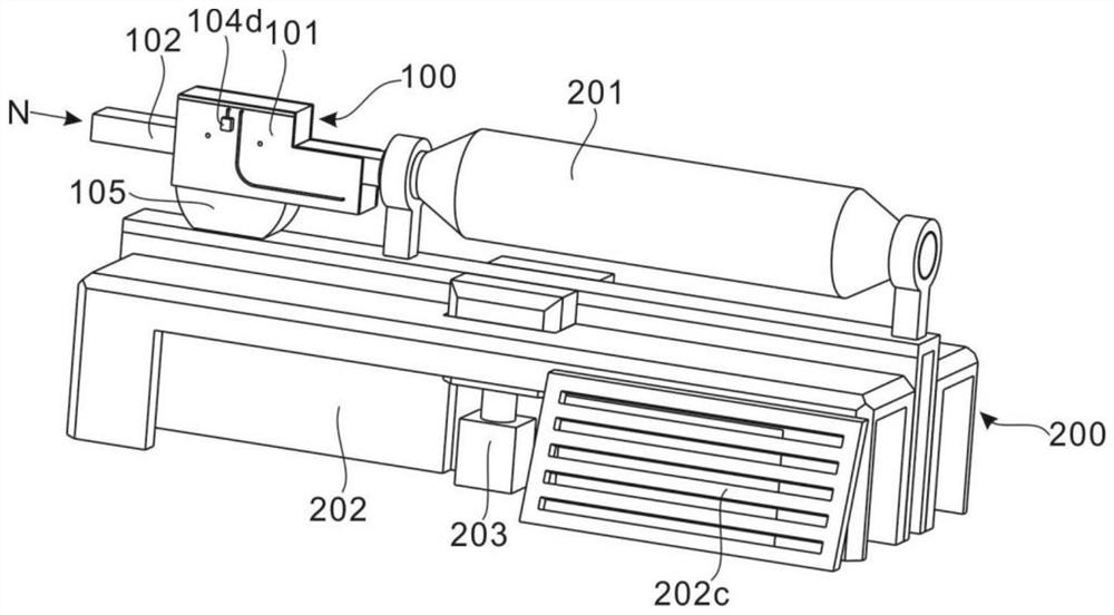
[0029] refer to Figure 1-9 , which is the first embodiment of the present invention, this embodiment provides a denitration reactor pre-dust removal device, which can be installed in any denitration reactor in the prior art to improve the purification efficiency and maintenance efficiency of the denitration reactor .
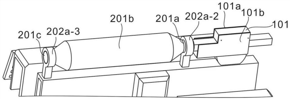
[0030] Specifically, the pre-dust removal unit 100 includes an outer casing 101, a connecting flue 102 arranged in the outer casing 101 and extending outward at both ends, a dust removal maintenance component 103 arranged in the outer casing 101, and the The blower assembly 104 connected to the dust removal maintenance assembly 103 and the collection box 105 arranged at the bottom of the outer casing 101 .
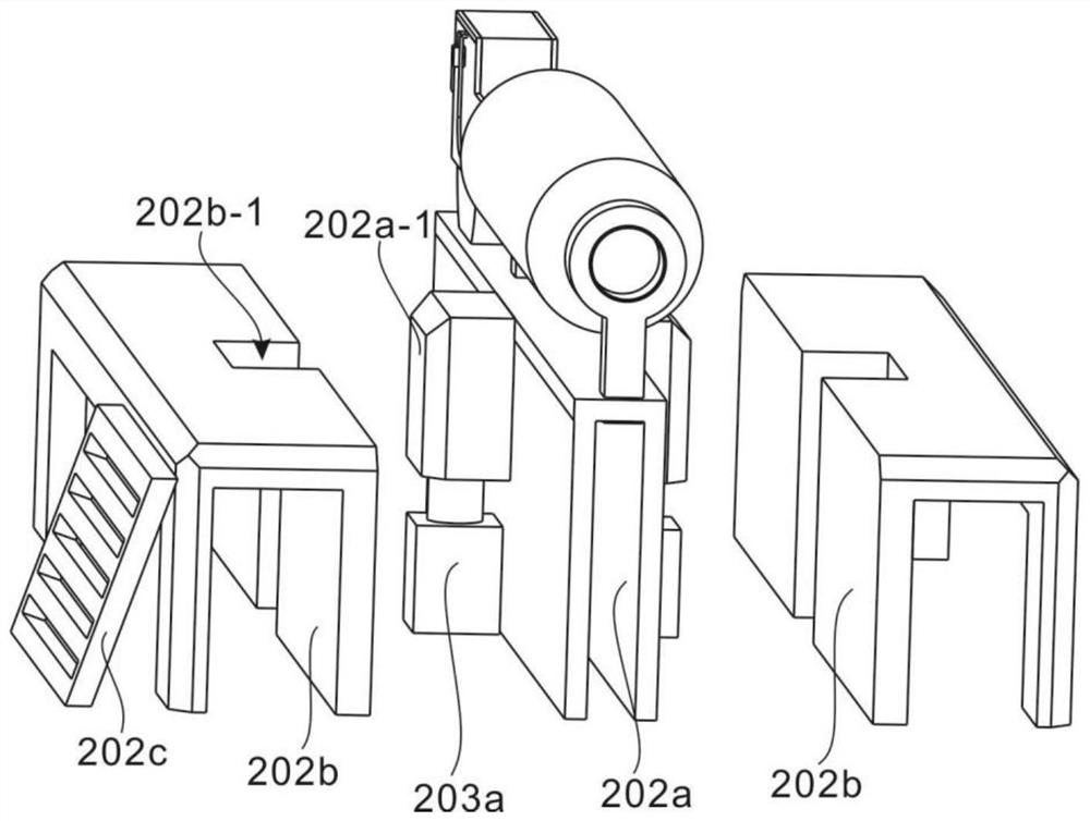
[0031] The reaction unit 200 includes a denitration reactor 201 , an inspection platform 202 arranged at the bottom of the denitration reactor 201 , and a lifting assembly 203 connected to the inspection platform 202 .
[0032] Further, the denitration re...
PUM
 Abstract
Description
Claims
Application Information