Composite damping plate for low and medium frequency noise reduction switching

A compound damping and noise reduction technology, applied in the field of acoustic metamaterials, can solve the problems of being too thick, poor noise elimination effect, and difficult to use flexibly, so as to achieve good sound absorption performance, improve sound insulation coefficient, and improve noise treatment effect.

Active Publication Date: 2021-12-17
深圳市百代亚星科技有限公司
View PDF8 Cites 0 Cited by
  • Summary
  • Abstract
  • Description
  • Claims
  • Application Information

AI Technical Summary

Problems solved by technology

[0004] In the prior art, most of the treatment methods for reducing low-frequency vibration and noise are sound insulation materials and damping materials through the conversion of sound energy. However, when traditional materials are used to isolate sound waves and vibrations, the thickness and size of the sound insulation material components are generally required. The wavelength of the sound wave matches, that is, the longer the wavelength of the sound wave, the thicker the thickness of the sound insulation material required. Although some metal materials have good sound insulation ability, the cost is too high, too heavy, and it is difficult to use flexibly
Existing damping materials can play a role in dispelling low-frequency noise, but the effect is single. In the face of noise of different frequencies, the existing damping plate either has insufficient frequency and noise reduction capabilities, poor noise elimination effect, or single noise reduction frequency. The noise processing effect is better only at a certain frequency

Method used


Image

  • Composite damping plate for low and medium frequency noise reduction switching
  • Composite damping plate for low and medium frequency noise reduction switching
  • Composite damping plate for low and medium frequency noise reduction switching

Examples


Embodiment Construction

[0030] The present invention will be described in detail below in conjunction with the implementations shown in the drawings, but it should be noted that these implementations are not limitations of the present invention, and those of ordinary skill in the art based on the functions, methods, or structural changes made by these implementations Equivalent transformations or substitutions all fall within the protection scope of the present invention. It should be noted that, in the case of no conflict, the embodiments in the present application and the features in the embodiments can be combined with each other.

[0031] In the description of the present application, it should be understood that the terms "center", "longitudinal", "transverse", "upper", "lower", "front", "rear", "left", "right", " The orientation or positional relationship indicated by "vertical", "horizontal", "top", "bottom", "inner", "outer", etc. is based on the orientation or positional relationship shown i...


PUM


Abstract

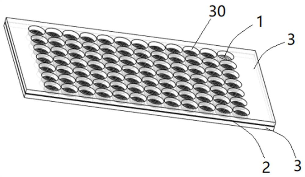
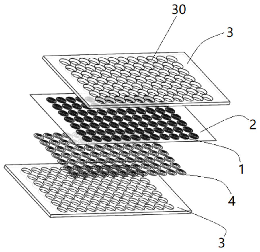
The invention provides a composite damping plate for low and medium frequency noise reduction switching. The composite damping plate comprises mass strips, a sticky elastic film layer and composite layers. A plurality of mass strips are arranged, the mass strips are in a circular ring shape and are arranged in a concentric circle grouping mode, the peripheries of the mass strips are wrapped and wound with electro-sensitive expansion strips, the electro-sensitive expansion strips are connected with a circuit controller through wires, and the mass strips are bonded through the sticky elastic thin film layers in a pouring mode; the composite layers are located on the outer side of the composite damping plate and provided with a plurality of through holes, and the composite layers are correspondingly pressed to the two sides of the viscous elastic film layer through a viscous state damping rubber material; and the electro-sensitive expansion strips change the surface tension of the viscous elastic film layer between the adjacent mass strips in a power-on expansion manner. According to the composite damping plate for low and medium frequency noise reduction switching, noise of different frequencies can be reduced, and the noise reduction performance and the noise reduction effect are improved.

Description

technical field [0001] The invention relates to the technical field of acoustic metamaterials, and more specifically relates to a composite damping plate for middle and low frequency noise reduction switching. Background technique [0002] Low-frequency vibration and noise problems are ubiquitous in equipment such as automobiles, trains, aircraft, and ships. Due to the slow attenuation and strong penetration of low-frequency vibration and noise capabilities, it is difficult to obstruct and control them, which seriously restricts the performance of these equipment. The ride comfort even directly affects the equipment operation and the health and life safety of the passengers. [0003] Acoustic metamaterials refer to artificial subwavelength structures with negative equivalent mass density or negative equivalent modulus. In 2000, the band gap frequency of ordinary phononic crystals was reduced by two orders of magnitude, breaking through the limit of Bragg scattering and reach...

Claims


Application Information

Patent Timeline
Patent Type & Authority Applications(China)
IPC IPC(8): B32B5/02B32B5/26B32B3/08B32B3/24B32B7/12B32B33/00B60R13/08B61D17/18B63B3/68B64C1/40
CPCB32B5/02B32B5/26B32B3/085B32B3/266B32B7/12B32B33/00B60R13/08B61D17/185B63B3/68B64C1/40B32B2307/102B32B2250/20B32B2605/08B32B2605/10B32B2605/18B32B2605/12
Inventor 郑莉莉路宽任香苇
Owner 深圳市百代亚星科技有限公司
Why Eureka
Try Eureka