

Waste engine oil catalytic cracking device
A technology for catalytic cracking and waste engine oil, which is applied in catalytic cracking, cracking, petroleum industry, etc. It can solve the problems of reducing the utilization rate of waste engine oil, clogging of the liquid distribution pipe, and affecting the working effect of the liquid separation pipe, so as to enhance the cleaning effect and improve The effect of collecting effects
- Summary
- Abstract
- Description
- Claims
- Application Information
AI Technical Summary
Problems solved by technology
Method used
Image

Examples
Embodiment
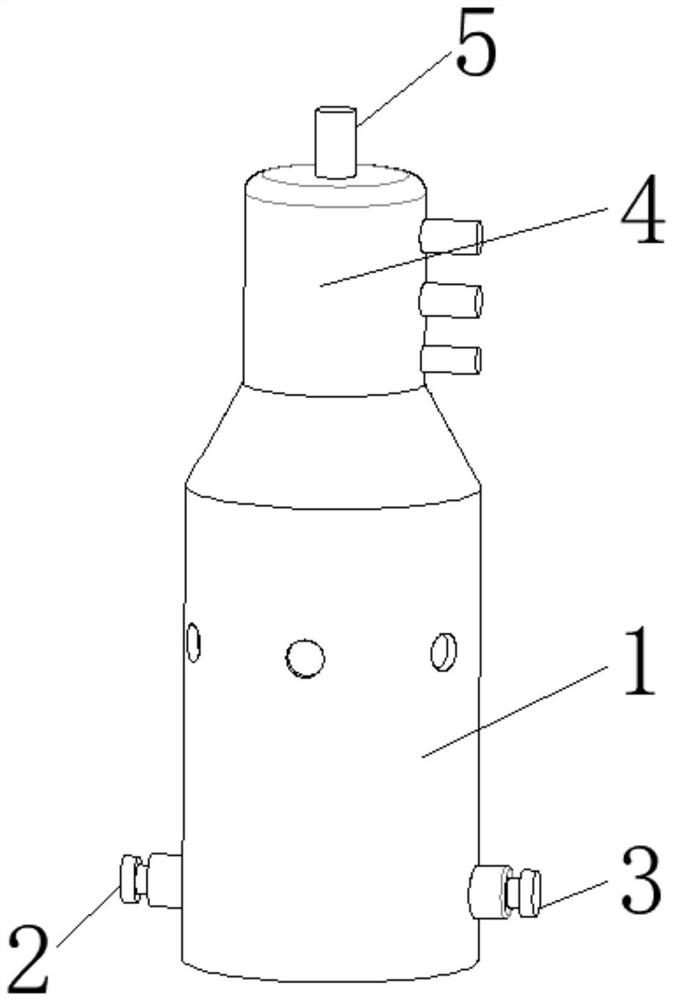
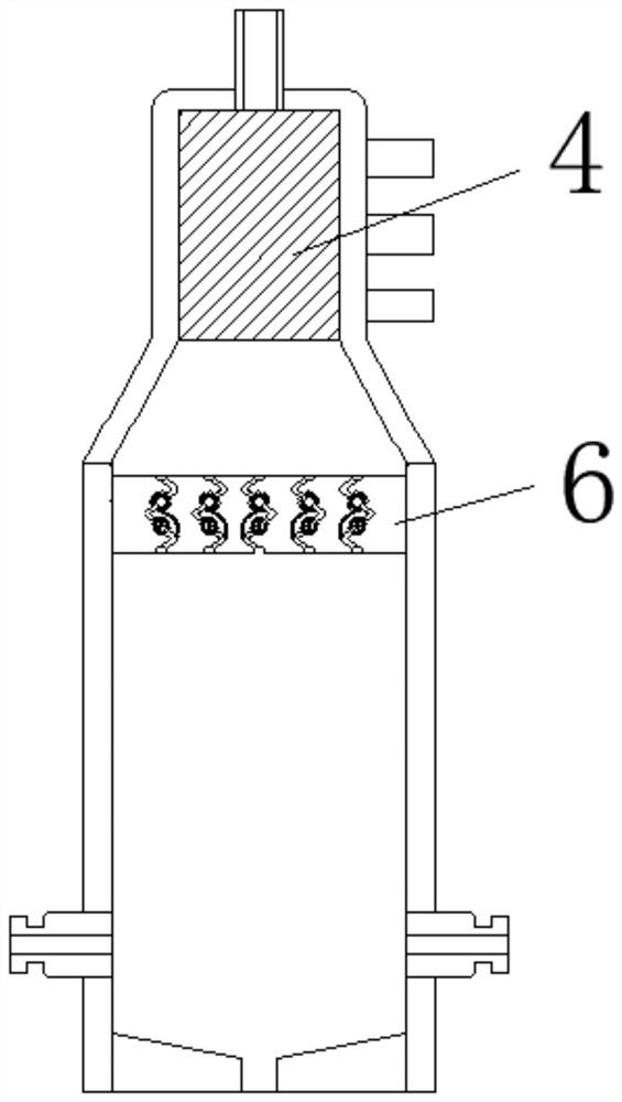
[0030] Such as Figure 1-8 As shown, the embodiment of the present invention provides a waste engine oil catalytic cracking device, including a reaction tank 1, a feed pipe 2, an air intake pipe 3, a liquid separator 4 and an exhaust pipe 5, and the feed pipe 2 is arranged on one side of the reaction tank 1. The side outer wall, the inlet pipe 3 is arranged on the other side outer wall of the reaction tank 1, the inlet pipe 3 and the feed pipe 2 are all connected with the reaction tank 1, one end of the inlet pipe 3 is connected with the output end of the air pump, and the liquid pipe 4 It is arranged on the outer wall of the top of the reaction tank 1, the waste gas pipe 5 is arranged on the outer wall of one end of the liquid pipe 4, the outer wall of the bottom end of the reaction tank 1 is provided with a slag outlet, and the inner wall of the reaction tank 1 is provided with a filter plate mechanism.
[0031]In the present invention, the filter plate mechanism includes a ...
PUM
 Abstract
Description
Claims
Application Information