
Recycling system for continuously discharging fluid into surface type condenser

A technology for discharging fluid and recovery system, which is applied in steam/steam condensers, lighting and heating equipment, etc., and can solve the problem that the heat of the working medium is not well utilized.

Pending Publication Date: 2021-12-17
XIAN THERMAL POWER RES INST CO LTD
View PDF5 Cites 0 Cited by
  • Summary
  • Abstract
  • Description
  • Claims
  • Application Information

AI Technical Summary

Problems solved by technology

[0006] The purpose of the present invention is to overcome the above-mentioned shortcoming of the prior art, provide a kind of recovery system that discharges fluid continuously and enters the surface condenser, to solve the problem that the heat of working medium is not well utilized in the prior art

Method used


Image

  • Recycling system for continuously discharging fluid into surface type condenser
  • Recycling system for continuously discharging fluid into surface type condenser
  • Recycling system for continuously discharging fluid into surface type condenser

Examples


Embodiment Construction

[0030] The present invention is described in further detail below in conjunction with accompanying drawing:

[0031] In the description of the present invention, it should be noted that the terms "center", "upper", "lower", "left", "right", "vertical", "horizontal", "inner", "outer" etc. The indicated orientation or positional relationship is based on the orientation or positional relationship shown in the drawings, and is only for the convenience of describing the present invention and simplifying the description, rather than indicating or implying that the referred device or element must have a specific orientation, or in a specific orientation. construction and operation, and therefore cannot be construed as limiting the present invention; the terms "first", "second", and "third" are used for descriptive purposes only, and cannot be construed as indicating or implying relative importance; in addition, unless otherwise Clearly stipulated and limited, the terms "installation"...


PUM


Abstract

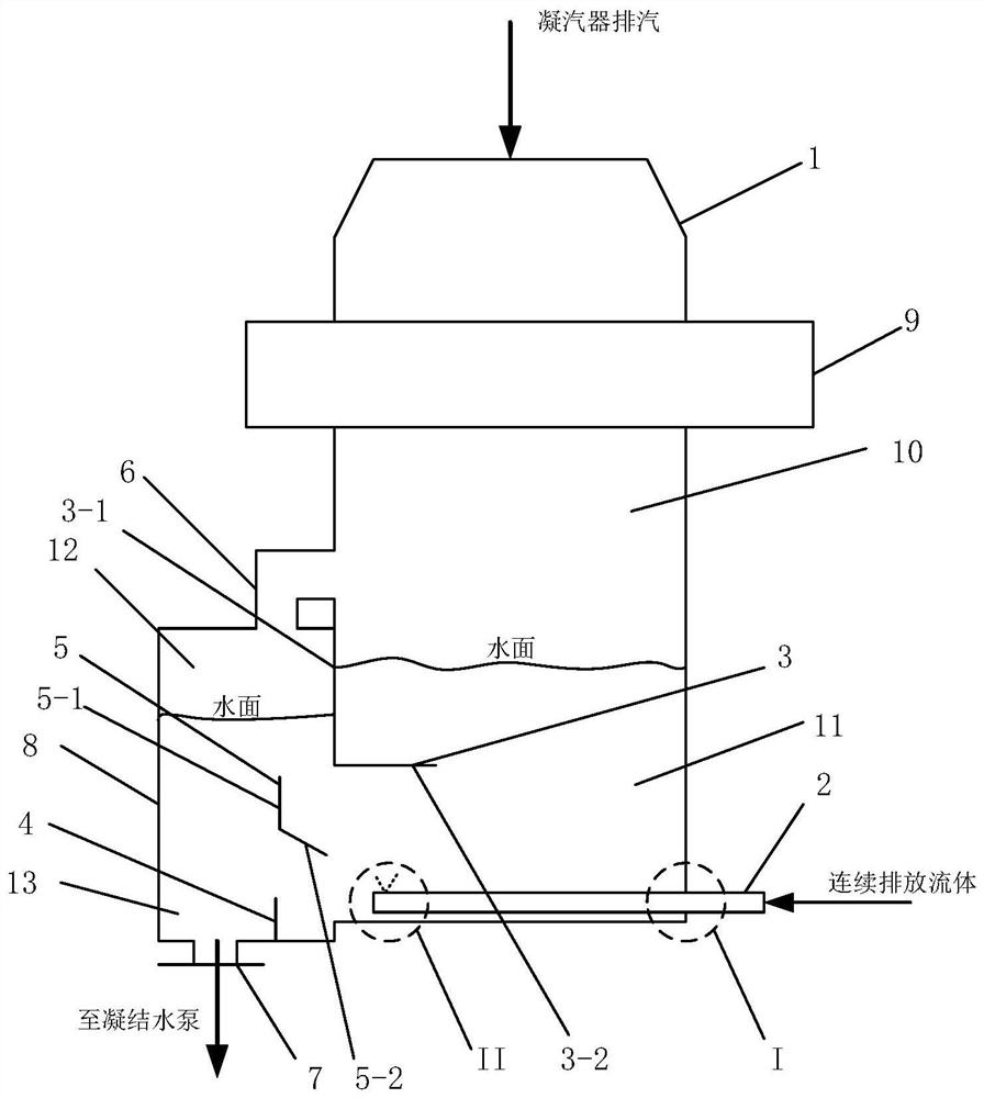
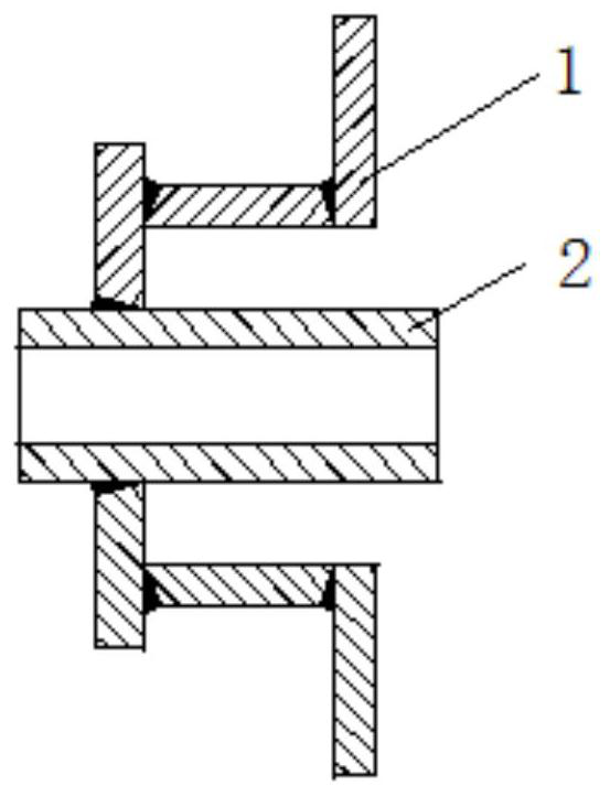
The invention discloses a recycling system for continuously discharging fluid into a surface type condenser. The recycling system comprises the condenser, a fluid distribution header and a steam-water separator, the steam-water separator is arranged on one side of the condenser and communicates with the condenser, the water side and the steam side both communicate with the condenser, the fluid distribution header is inserted into the water side of the condenser from the other end of the condenser, and the outer end of the fluid distribution header is connected with the fluid. According to the system, 'continuous discharge fluid' can be introduced below a hot well of the condenser, heat of the working medium can be effectively recycled while the working medium is recycled, the supercooling degree of condensed water is eliminated, and safe and stable operation of a unit cold end system is not affected. Under the condition of meeting stable operation of the unit, the working medium is recycled, and the heat energy is further effectively utilized.

Description

technical field [0001] The invention belongs to the technical field of energy saving and consumption reduction of coal-fired units, and in particular relates to a recovery system for continuously discharging fluid into a surface condenser. Background technique [0002] The steam discharged from the thermal power unit to the condenser is mainly divided into three categories according to the steam quality: 1. Low-level steam discharge: including auxiliary steam turbine steam discharge, steam discharge below one atmospheric pressure, and steam discharge with a flow rate below 0.5t / h and high pressure Steam discharge; 2. Medium-level steam discharge: including steam discharge with a flow rate of 0.5-10t / h and a pressure of 0.035-1.75MPa; 3. High-energy steam discharge: including pressure greater than 1.75MPa or enthalpy greater than 2907kJ / kg And steam discharge with a flow rate greater than 10t / h. [0003] Generally speaking, for steam discharge with a steam flow rate below 10...

Claims


Application Information

Patent Timeline
Patent Type & Authority Applications(China)
IPC IPC(8): F28B1/02F28B9/04F28B11/00
CPCF28B1/02F28B9/04F28B11/00
Inventor 邹洋马汀山荆涛万超王明勇韩立李高潮贾明晓杨珍帅
Owner XIAN THERMAL POWER RES INST CO LTD
Learn More