
Advanced geological forecasting method and system based on cross-advanced horizontal drilling earthquake CT

A technology of advanced geological prediction and horizontal drilling, which is applied in seismology, seismic energy generation, seismic signal transmission, etc., can solve the problems of attenuation of prediction accuracy, inability to detect, and inability to meet the requirements of refined detection, etc., to achieve high-precision detection, Guarantee the safety of tunnel construction and the effect of high technical resolution

Pending Publication Date: 2021-12-17
中铁二院成都工程检测有限责任公司
View PDF0 Cites 0 Cited by
  • Summary
  • Abstract
  • Description
  • Claims
  • Application Information

AI Technical Summary

Problems solved by technology

[0003] The existing problems and defects of the existing technology are as follows: 1. The commonly used advanced geological forecasting methods are to arrange the observation system on the excavated surface, and its forecasting accuracy will decrease with the increase of the detection distance, which cannot meet the requirements of refined detection
2. The application of conventional cross-hole seismic CT technology is usually based on vertical holes, and is applied to the detection of geological conditions in the vertical direction of the surface. Before tunnel excavation, it is necessary to detect the geological conditions in front of the tunnel face, that is, in the horizontal direction. Therefore, the conventional Cross-hole seismic CT technology cannot be applied to the detection of geological conditions in front of the tunnel face

Method used


Image

  • Advanced geological forecasting method and system based on cross-advanced horizontal drilling earthquake CT
  • Advanced geological forecasting method and system based on cross-advanced horizontal drilling earthquake CT
  • Advanced geological forecasting method and system based on cross-advanced horizontal drilling earthquake CT

Examples


Embodiment Construction

[0027] In order to make the object, technical solution and advantages of the present invention more clear, the present invention will be further described in detail below in conjunction with the examples. It should be understood that the specific embodiments described here are only used to explain the present invention, and are not intended to limit the present invention. It should be emphasized in the present invention that replacing seismic CT with electromagnetic CT can also achieve fine detection of geological conditions in front of the tunnel face , and the implementation of electromagnetic CT in the field is more convenient.

[0028] Aiming at the problems existing in the prior art, the present invention provides an advanced geological prediction method and system based on seismic CT across advanced horizontal boreholes. The present invention will be described in detail below with reference to the accompanying drawings.

[0029] like figure 1 As shown, the advanced geo...


PUM


Abstract

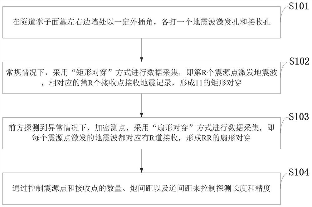
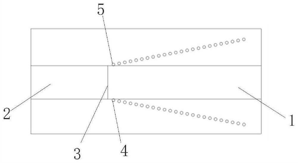
The invention belongs to the technical field of tunnel advanced geology forecasting, and discloses an advanced geological forecasting method and system based on a cross-advanced horizontal drilling earthquake CT. The method comprises the steps that: a seismic wave excitation hole and a seismic wave receiving hole are formed in the positions, close to the left side wall and the right side wall, of a tunnel face at a certain external insertion angle; under a conventional condition, data acquisition is carried out by adopting a rectangular opposite penetration mode; and when an abnormal condition is detected in front, measuring points are encrypted, and data acquisition is carried out by adopting a fan-shaped opposite penetration mode. The detection length and precision are controlled by controlling the number of seismic source points and receiving points, the shot distance and the channel distance. One advanced horizontal drill hole is provided with R seismic source points, and the other advanced horizontal drill hole is provided with R receiving points. According to the system, a tunnel face is arranged between an unexcavated tunnel section and an excavated section, and a seismic wave excitation hole and a seismic wave receiving hole are formed in the positions, close to the left side wall and the right side wall, of the tunnel face at a certain external insertion angle respectively. According to the invention, precise forecasting of the geological condition in front of the tunnel face is realized.

Description

technical field [0001] The invention belongs to the technical field of advanced geological prediction of tunnels, and in particular relates to an advanced geological prediction method and system based on seismic CT across advanced horizontal boreholes. Background technique [0002] At present, the advanced tunnel geological prediction methods commonly used at home and abroad, such as seismic wave reflection method, geological radar method, time-domain transient electromagnetic method, etc., all deploy observation systems on the excavated surface, and their prediction accuracy will decrease with the increase of detection distance. Cross-bore seismic CT technology is a high-tech detection technology based on the detection and identification of abnormal regions based on elastic wave velocity differences between media. It is the product of the combination of modern seismic digital observation technology and computer technology. Fine detection. This technology has been widely us...

Claims


Application Information

Patent Timeline
Patent Type & Authority Applications(China)
IPC IPC(8): G01V1/22G01V1/24G01V1/157
CPCG01V1/22G01V1/24G01V1/157
Inventor 宋振东曹化平牟元存王树栋高树全张新平汪文强
Owner 中铁二院成都工程检测有限责任公司
Learn More