
Automatic material overturning device for electron beam irradiation production and turnover treatment system

A technology of electron beam irradiation and automatic material turning, which is applied in the direction of irradiation device, transportation and packaging, conveyor objects, etc., can solve the problems of high labor cost, low turning speed, and reduced processing efficiency of the processing system, so as to reduce labor costs. cost, efficiency improvement, uniformity improvement effect

Pending Publication Date: 2021-12-17
浙江韩情辐照技术有限公司
View PDF0 Cites 0 Cited by
  • Summary
  • Abstract
  • Description
  • Claims
  • Application Information

AI Technical Summary

Problems solved by technology

[0003] In the current irradiation treatment process, the form of a conveyor belt is usually used to pass the goods to be irradiated under the irradiation emitter, and the electron beam emitted from the emitter is used to irradiate the goods. The effect is to make the uniformity of the irradiation dose. The front and back sides of the goods need to be irradiated in both directions. Therefore, during the irradiation process, it is necessary to irradiate the top of the goods first, and then unload the goods manually, and then turn them over. The reverse side of the goods is also irradiated; manual turning requires specific operators to operate, and the labor cost is relatively high, and the turning speed may be slower during the turning process, resulting in a reduction in the processing efficiency of the entire treatment system and affecting radiation. According to production efficiency

Method used


Image

  • Automatic material overturning device for electron beam irradiation production and turnover treatment system
  • Automatic material overturning device for electron beam irradiation production and turnover treatment system
  • Automatic material overturning device for electron beam irradiation production and turnover treatment system

Examples


Embodiment 1

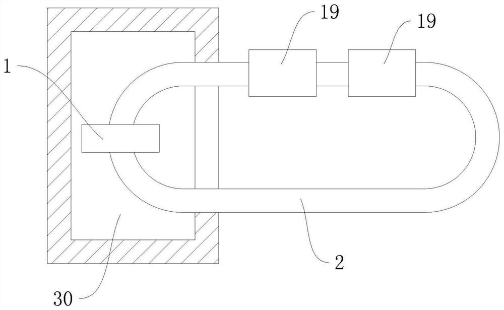
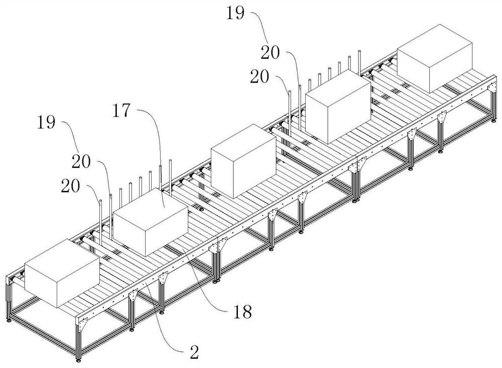
[0046] This embodiment discloses an electron beam irradiation production turnover processing system, such as Figure 1-4 and Figure 9 As shown, based on the conveyor belt 2 in a closed-loop structure, the goods 17 are prevented from being conveyed circularly above the conveyor belt 2. The conveyor belt 2 is formed by arranging a number of feeding rollers 18. material device, two sets of automatic turning devices are distributed along the direction of the feeding belt, capable of turning over the front and back sides of the goods 17; it also includes an electron beam irradiation system, the irradiation chamber 30 of the electron beam irradiation system passes through the conveyor belt 2 during transportation, For radiation shielding and protection, the electron beam irradiation system includes an irradiation box 1, which is installed above the conveyor belt 2, electron beams are emitted from the bottom of the irradiation box 1, and the goods 17 on the conveyor belt 2 are irrad...

Embodiment 2

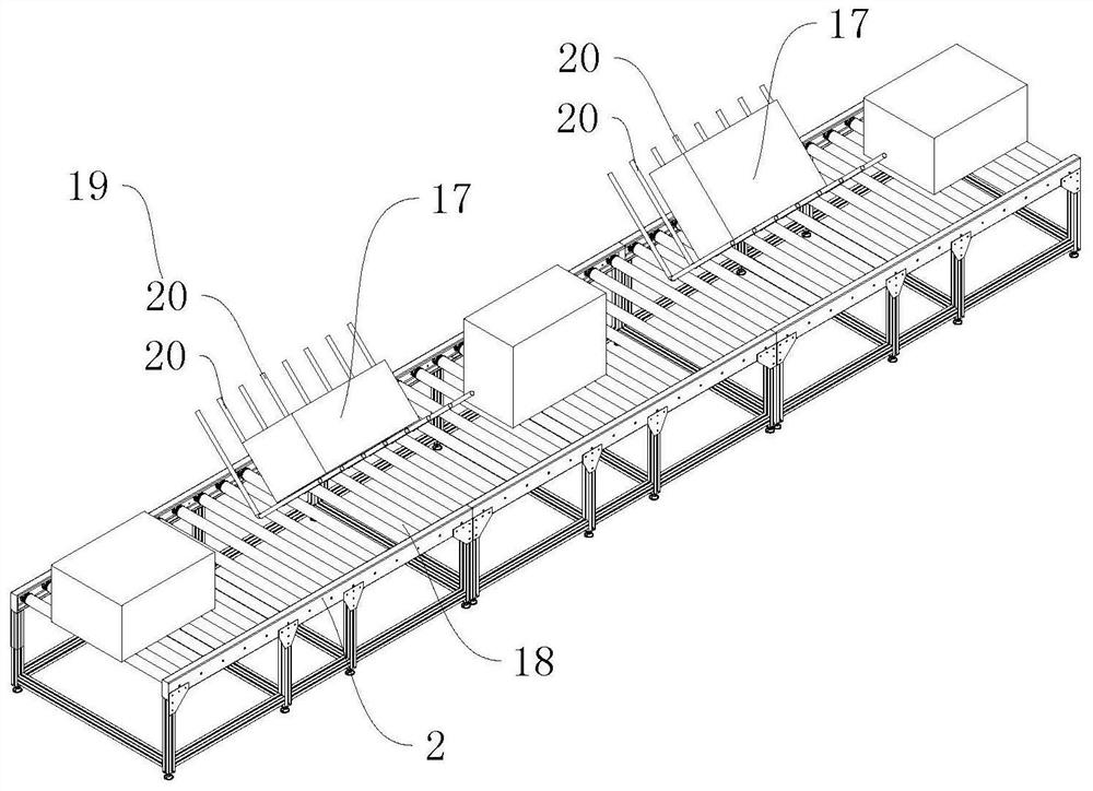
[0049] This embodiment discloses a production turnover processing system for electron beam irradiation. On the basis of Embodiment 1, the automatic material turning device is optimized and referred to Figure 1-6 shown in detail.

[0050] Automatic material turning device comprises material turning assembly 19, is installed on the conveyer belt 2 that is arranged by several feeding rollers 18, and material turning assembly 19 comprises material turning frame 20, and the partial structure of material turning frame 20 passes between feeding rollers 18. through, so that the goods 17 above can be supported and turned over; the turning frame 20 has a number of turning bars 201 bent at right angles, and two supporting seats 21 and two connecting rods 22 are installed on the lower part of the feeding roller 18, Two support bases 21 are fixedly installed on the lower both sides of the feed roller 18, one end of the connecting rod 22 is hinged to the support base 21, and the other end ...

Embodiment 3

[0058] This embodiment discloses a protection device for goods 17 irradiated by electron beams, and the protection device can be installed and used in an electron beam irradiation production turnover processing system in the above-mentioned embodiments;

[0059] refer to Figure 10 As mentioned above, the protective device includes a protective plate 4 and a driving mechanism 6. The protective plate 4 is located at the electron beam emitting end of the radiation box. Generally, the irradiation box 1 is a triangular cover with a large bottom and a small top. Fixed, the electron beam is emitted from the emission end of the radiation box, and the cargo 17 below is irradiated; the protective plate 4 is located at the emission end of the lower part of the irradiation box 1; The beam is shielded, generally by a lead plate that is impenetrable to electron beam radiation.

[0060] Generally, corresponding cargo 17 conveying lines are installed in the irradiation system, which drives ...


PUM


Abstract

The invention discloses an automatic material overturning device for electron beam irradiation production and a turnover treatment system, relates to the technical field of electron beam irradiation equipment, and aims to solve the problem that the processing efficiency is affected as goods need to be turned over manually in the electron beam irradiation treatment process. According to the technical scheme, the automatic material overturning device is characterized by comprising a material overturning assembly arranged on a conveying belt formed by arranging a plurality of feeding rollers, the material overturning assembly comprises a material overturning frame, the material overturning frame comprises a plurality of material overturning rods bent in a right-angle mode, two supporting seats and two connecting rods are arranged on the lower parts of the feeding rollers, the two supporting seats are fixedly installed on the two sides of the lower parts of the feeding rollers, one end of the connecting rod is hinged to the supporting seat, and the other end of the connecting rod is hinged to one side of the material overturning rod; and a hinge joint is fixedly connected to the outer corner of the bending angle of the material overturning rod. The automatic material overturning device further comprises a swing mechanism, wherein the swing mechanism is connected with the hinge joint and used for driving the material overturning rods to swing in a reciprocating mode. The goods to be irradiated can be overturned, and automation of goods overturning is achieved.

Description

technical field [0001] The invention relates to the technical field of irradiation equipment, more specifically, it relates to an automatic material turning device for electron beam irradiation production, and also relates to a turnover processing system for electron beam irradiation production. Background technique [0002] Irradiation processing is different from traditional mechanical processing and thermal processing technology, so it is known as the third revolution of human processing technology. It is characterized by the strong penetrating ability of the rays released by the radioactive source. It can go deep into the substance for "processing", which is carried out at room temperature. Since the processor is the high-energy ray and the highly active intermediates caused by it, rather than the thermal movement of molecules, it has low energy consumption, no residue, and no environmental problems. So it's clean processing technology. Moreover, its reaction is easy t...

Claims


Application Information

Patent Timeline
Patent Type & Authority Applications(China)
IPC IPC(8): G21K5/10B65G47/248
CPCG21K5/10B65G47/248
Inventor 汪恩锋唐昌王俏珍黄晓锋
Owner 浙江韩情辐照技术有限公司
Learn More