
Cathode-grid assembly and electron gun

A component and cathode grid technology, which is applied in the field of electron guns, can solve the problems of smaller spacing between cathode grids, damage, difficulty in realizing high-current and strong electron beam extraction, and achieve the effect of increasing heat dissipation

Active Publication Date: 2021-12-17
INST OF HIGH ENERGY PHYSICS CHINESE ACADEMY OF SCI
View PDF5 Cites 1 Cited by
  • Summary
  • Abstract
  • Description
  • Claims
  • Application Information

AI Technical Summary

Problems solved by technology

If the grid temperature is too high, the high-temperature deformation of the grid will cause the spacing between the cathode and grid to become smaller or a short circuit between the cathode and the grid will occur, and the grid temperature will reach the melting point of the grid solder, which will cause the grid to be desoldered. The above problems make the cathode grid assembly impossible. Normal use or even damage
[0003] The structure of the existing cathode grid assembly makes it difficult to extract high current and intensity electron beams

Method used


Image

  • Cathode-grid assembly and electron gun
  • Cathode-grid assembly and electron gun
  • Cathode-grid assembly and electron gun

Examples


Embodiment Construction

[0031] The application will be further described in detail below in conjunction with the accompanying drawings and embodiments. It should be understood that the specific embodiments described here are only used to explain related inventions, rather than to limit the invention. It should also be noted that, for ease of description, only parts related to the invention are shown in the drawings.

[0032] It should be noted that, in the case of no conflict, the embodiments in the present application and the features in the embodiments can be combined with each other. The present application will be described in detail below with reference to the accompanying drawings and embodiments.

[0033] It should be noted that the terms "center", "longitudinal", "transverse", "length", "width", "thickness", "top", "bottom", "left", "right", "front", " Rear, Vertical, Horizontal, Top, Bottom, Inner, Outer, Clockwise, Counterclockwise, Axial, Radial, Circumferential The orientation or posit...


PUM

PropertyMeasurementUnit
sizeaaaaaaaaaa
diameteraaaaaaaaaa
areaaaaaaaaaaa

Abstract

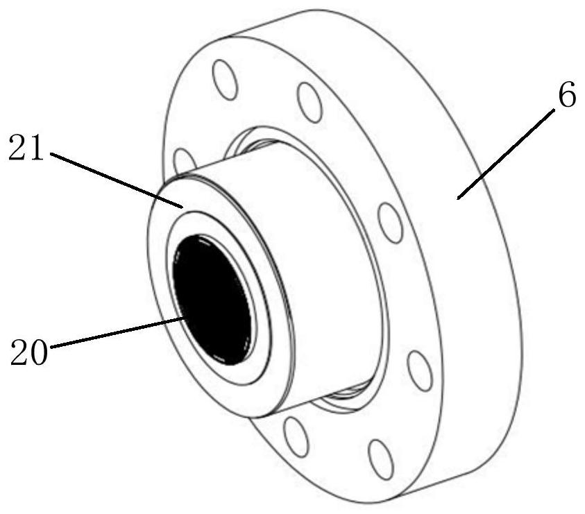
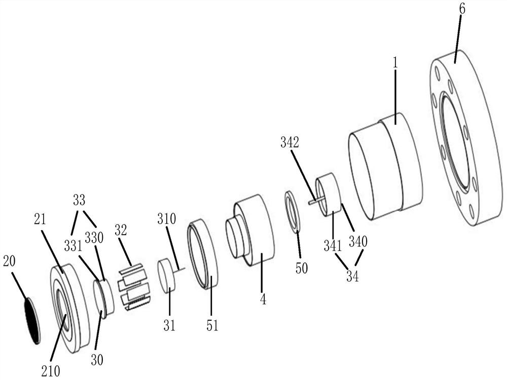
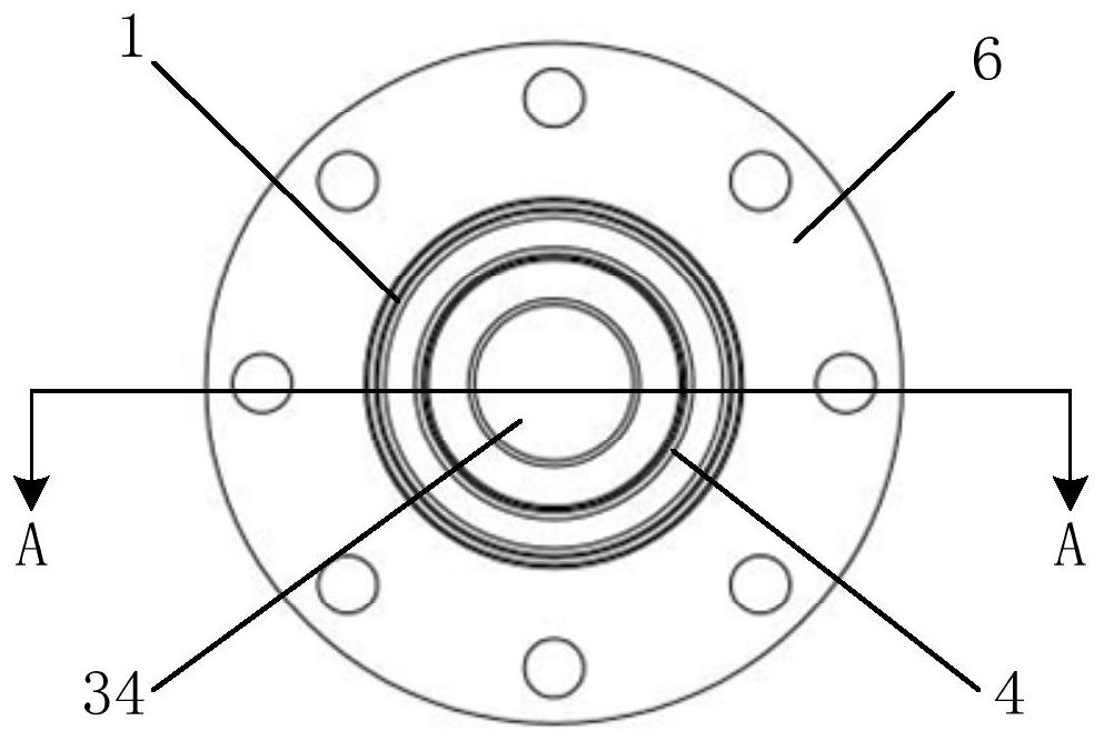
The embodiment of the invention discloses a cathode-grid assembly and an electron gun. The cathode-grid assembly comprises a shell, a grid component and a cathode component, wherein the grid component and the cathode component are located in the shell; the grid component comprises a grid mesh and a heat dissipation ring, and the grid mesh is arranged at an opening of the heat dissipation ring; the cathode component comprises a cathode and a heater used for heating the cathode, the cathode is close to the grid mesh, a gap is formed between the cathode and the grid mesh, the emitting face of the cathode faces the grid mesh, and the cathode and the heater are located in the hollow portion of the heat dissipation ring. The heat dissipation ring which is fixedly connected with the grid mesh and wraps the cathode and the heater is arranged, so that the heat dissipation performance of the grid component is improved, and the cathode-grid assembly can lead out high-flow-intensity electron beams.

Description

technical field [0001] The present application generally relates to the technical field of electron guns, and specifically relates to a cathode grid assembly and an electron gun. Background technique [0002] The cathode grid assembly is the key component of the electron gun in the electron linear accelerator, and is the source equipment for generating electron beams. In the working state, the grid in the cathode-grid assembly needs to bear high thermal power, which mainly comes from the thermal radiation on the surface of the cathode and the partial interception of the beam by the grid. For high-current-intensity cathode-grid components, in order to generate sufficient emission current intensity, it is often necessary to select a cathode with a larger area, resulting in a higher temperature for the grid due to more thermal radiation power and interception of more beam current. If the grid temperature is too high, the high-temperature deformation of the grid will cause the ...

Claims


Application Information

Patent Timeline
Patent Type & Authority Applications(China)
IPC IPC(8): H01J29/04H01J29/48H05H7/22
CPCH01J29/04H01J29/48H05H7/22
Inventor 何大勇王盛昌肖欧正李京祎
Owner INST OF HIGH ENERGY PHYSICS CHINESE ACADEMY OF SCI
Learn More