Electronic equipment installation cabinet

A technology for electronic equipment and cabinet installation, which is applied to the structural parts of electrical equipment, electrical components, and modification using gaseous coolant, etc. Ensure normal operation, avoid invalid consumption, and facilitate cooling effect

Inactive Publication Date: 2021-12-17
珠海城市职业技术学院
View PDF0 Cites 0 Cited by
  • Summary
  • Abstract
  • Description
  • Claims
  • Application Information

AI Technical Summary

Problems solved by technology

However, after the electronic equipment heats up, if the heat cannot be dissipated or discharged in time, it will definitely affect the normal operation of the electronic equipment. The installation of a large number of electronic equipment generally requires the use of a dedicated installation device. The installation device has an exhaust fan to increase the air volume of the electronic equipment. However, the airflow in the installation device at this stage is chaotic, and each area in the installation device is different due to the installation density and type of equipment. As a result, the heat dissipation effect of some equipment is not good, and eventually the heat dissipation performance of the installation device is not good, and the air volume of the exhaust fan cannot be fully used, resulting in waste

Method used


Image

  • Electronic equipment installation cabinet
  • Electronic equipment installation cabinet
  • Electronic equipment installation cabinet

Examples


Embodiment Construction

[0023] Embodiments of the present invention are described in detail below, and examples of the embodiments are shown in the drawings, wherein the same or similar reference numerals denote the same or similar elements or elements having the same or similar functions throughout. The embodiments described below by referring to the figures are exemplary only for explaining the present invention and should not be construed as limiting the present invention.

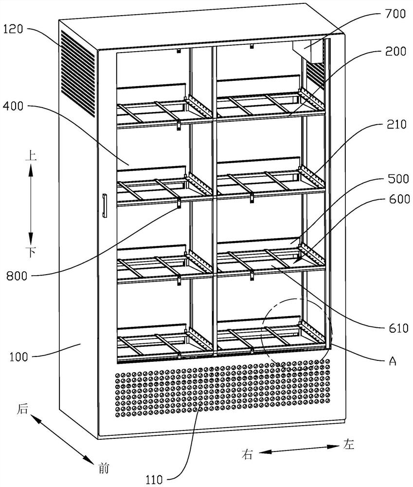
[0024] In the description of the present invention, it should be understood that the orientation descriptions, such as up, down, front, back, left, right, etc. indicated orientation or positional relationship may be based on the orientation or positional relationship shown in the accompanying drawings, only It is for the convenience of describing the present invention and simplifying the description, but does not indicate or imply that the referred device or element must have a specific orientation, be constructed and operated ...


PUM


Abstract

The invention discloses electronic equipment installation cabinet, which comprises a cabinet body, a supporting frame, an air cooler, a wind channel, a wind discharge device, a plurality of adjusting plates and a plurality of wind guide grooves, wherein a wind inlet is formed in the bottom of the cabinet door of the cabinet body, wind discharge ports are formed in the upper portions of the left side wall and the right side wall of the cabinet body, the supporting frame comprises a plurality of mounting mechanisms used for erecting electronic equipment, the first wind inlet of the air cooler is communicated with the wind inlet, a second wind inlet communicated with the first wind outlet of the air cooler is formed in the bottom of the wind channel, second wind outlets are formed in the areas, corresponding to the lower portions of the mounting mechanisms, of the front wall of the wind channel, the adjusting plates are slidably arranged on the wind channel to adjust the sizes of the second wind outlets, one end of the wind guide groove communicates with the second wind outlet, an opening of the wind guide groove faces upwards and is located below the mounting mechanism, and the third wind outlet of the wind discharge device is communicated with the wind discharge ports. According to the invention, the wind volume of each second wind outlet is controlled by sliding each adjusting plate, so that the wind volume can be reasonably distributed, and the temperature of each electronic equipment is effectively reduced.

Description

technical field [0001] The invention relates to the technical field of electromechanical equipment, in particular to an electronic equipment installation cabinet. Background technique [0002] Conductors except superconductors have large or small resistances. The existence of resistances leads to the occurrence of heating during power transmission and power use, especially electronic equipment. Electronic equipment has the characteristics of complex circuits and a large number of first-level electronic components. Therefore, it generates a huge amount of heat, and the temperature of electronic equipment can reach an astonishing sixty to seventy degrees under continuous long-term work. For example, common routers, switches, relays, and signal transmitting equipment, etc., work for a long time and are under heavy load, so their heat generation will naturally be large. However, after the electronic equipment heats up, if the heat cannot be dissipated or discharged in time, it ...

Claims


Application Information

Patent Timeline
Patent Type & Authority Applications(China)
IPC IPC(8): H05K7/20
CPCH05K7/20136H05K7/20145H05K7/20209H05K7/20172
Inventor 唐春华马旭王小磊王锦潮贺艳苓龚国围
Owner 珠海城市职业技术学院
Why Eureka
Try Eureka