Mixing device for preparing plaster for treating cancer pain
A technology of mixing device and cancer pain is applied in the field of drug preparation, which can solve the problems of easy agglomeration of solid drugs and difficulty in cleaning the inner wall of the device, and achieve the effect of increasing carbonization efficiency.
- Summary
- Abstract
- Description
- Claims
- Application Information
AI Technical Summary
Problems solved by technology
Method used
Image

Examples
Embodiment 1
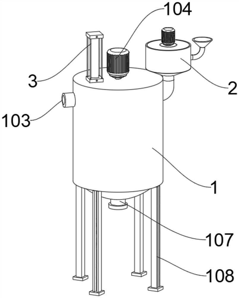
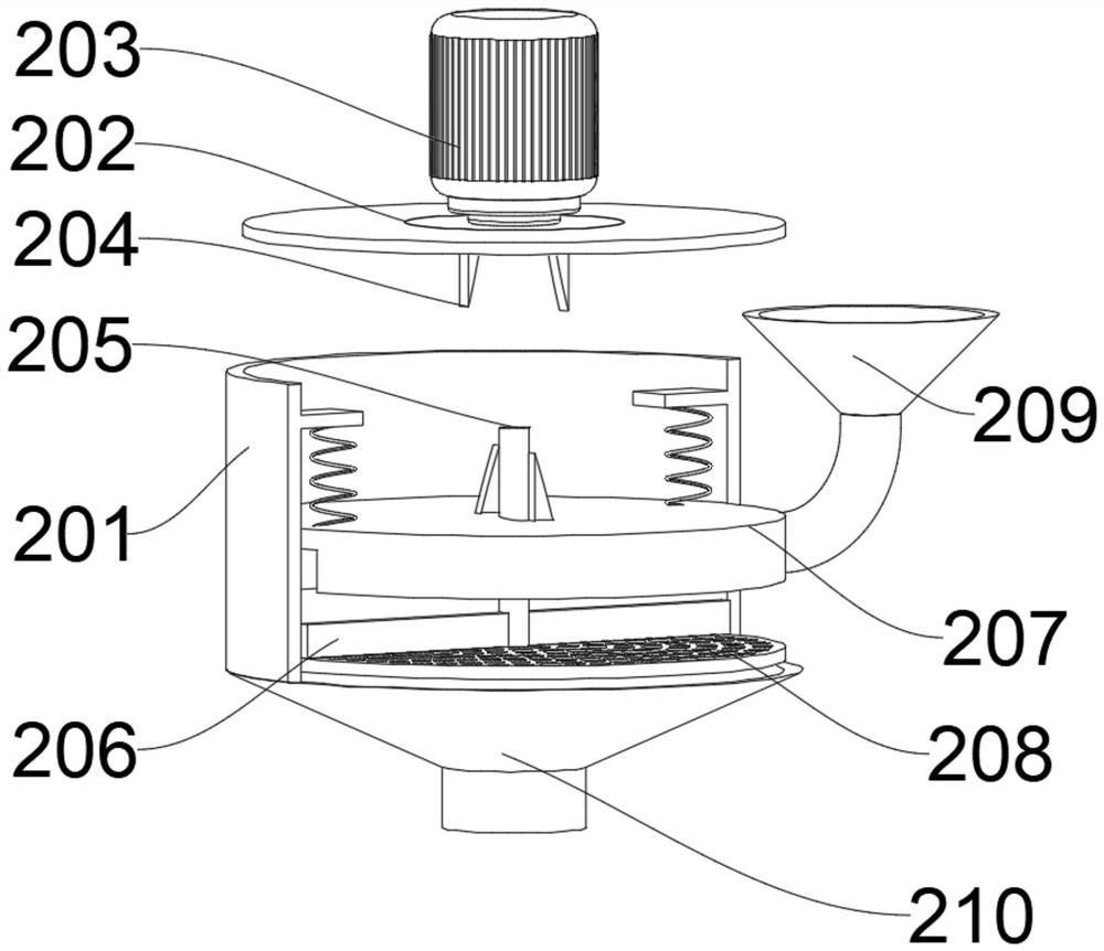
[0030] Please refer to Figure 1-2, a mixing device for treating cancer pain plaster, including a mixing device 1, the mixing device 1 includes a protective shell 101, the inside of the protective shell 101 is provided with a water bath layer 102, and the inside of the water bath layer 102 is provided with Stirring layer, solid feeding device 2 and water inlet 103 are respectively arranged on both sides of the top of the stirring layer, an opening and closing device 5 is arranged between the solid feeding device 2 and water inlet 103, and a control device is connected inside the opening and closing device 5 4. A cleaning device 3 is installed for the internal activities of the stirring layer.
[0031] The top of the protective case 101 is connected with a stirring motor 104, the output end of the stirring motor 104 is fixedly connected with a rotating shaft 105, the bottom of the protective case 101 is provided with a paste outlet 107, and the bottom of the protective case 101 i...
Embodiment 2
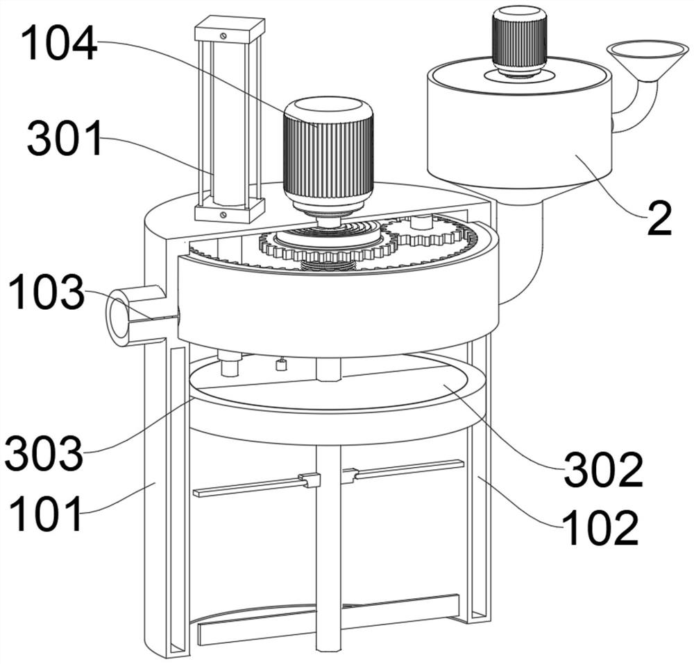
[0035] Please refer to Figures 3-4, the difference in connection with the basis of Embodiment 1 is that the cleaning device 3 includes a multi-stage hydraulic rod 301, and the multi-stage hydraulic rod 301 is fixedly installed on the top of the protective shell 101, and the multi-stage hydraulic rod 301 The bottom is fixedly connected with a lifting plate 302. The lifting plate 302 is located inside the stirring layer. There are slits inside the lifting plate 302. The outer side of the lifting plate 302 is covered with a rubber ring 303. The rubber ring 303 is in frictional contact with the inner wall of the stirring layer.
[0036] The present invention uses the cleaning device 3 to squeeze the paste from the device to the outside of the device after the stirring, and at the same time to clean the inside of the device. The working principle is: the lifting plate 302 is located on the top of the rotating shaft 105 when the cleaning device 3 is not working At this time, the lift...
Embodiment 3
[0038] Please refer to Figures 5-6, the difference between Embodiments 1 and 2 is that the opening and closing device 5 includes a control ring 504, which is fitted and installed on the inner wall of the protective case 101 and the control ring 504 is rotatable The outer side of the control ring 504 is provided with two feeding troughs 505, the two feeding troughs 505 correspond to the water inlet 103 and the discharge port 210 respectively, the inner gear 503 is welded on the inner side of the top of the control ring 504, and the outer side of the rotating shaft 105 is movable A sun gear 501 is sheathed, and a planetary gear 502 is meshed and connected between the sun gear 501 and the inner gear 503 .
[0039] The control device 4 includes a fixed ring 401. The fixed ring 401 is movably sleeved on the outside of the rotating shaft 105, and the top of the fixed ring 401 is fixedly connected with the top inner wall of the protective case 101. The outer side of the fixed ring 401...
PUM
 Abstract
Description
Claims
Application Information
 - Generate Ideas
- Intellectual Property
- Life Sciences
- Materials
- Tech Scout
- Unparalleled Data Quality
- Higher Quality Content
- 60% Fewer Hallucinations
Browse by: Latest US Patents, China's latest patents, Technical Efficacy Thesaurus, Application Domain, Technology Topic, Popular Technical Reports.
© 2025 PatSnap. All rights reserved.Legal|Privacy policy|Modern Slavery Act Transparency Statement|Sitemap|About US| Contact US: help@patsnap.com