Continuous carbonization apparatus and method

A technology of carbonization device and carbonization belt, which is applied in the direction of combustion method, incinerator, lighting and heating equipment, etc., and can solve the problems of high carbonization cost, increased equipment cost, and large installation space

Inactive Publication Date: 2005-04-13
C Y C +1
View PDF1 Cites 5 Cited by
  • Summary
  • Abstract
  • Description
  • Claims
  • Application Information

AI Technical Summary

Problems solved by technology

[0006] However, for the above-mentioned independent type carbonization device, since the maximum number of carbonization treatment can be determined each time, and each time must be carried out from the loading operation, through the carbonization treatment and cooling process, until the operation of discharging the cylinder A series of operations, these operations require labor and skilled technology, and a large amount of carbonized substances cannot be carbonized at the same time, so there is a problem that it is difficult to control the amount of carbonization, it takes more time than expected, and the production efficiency cannot be improved.
In addition, there are also problems of large energy waste and very high carbonization cost
[0007] In addition, there is a tendency for carbides to become large, and carbides with a suitable particle size for use as a soil conditioner cannot be obtained only in existing carbonization treatment devices, so a crusher as an accessory equipment is necessary, so there is a problem of increasing equipment costs. question
[0008] In this regard, the various rotary carbonization treatment devices described in Japanese Patent Laid-Open No. 11-37645, because the carbonization furnace is rotary, there is no need to use a pulverizer or the like to crush in the subsequent process, but there are the following problems: it must be required The material, shape, size and water content of the carbonized material are certain; when the moving carbide in the drum is excessively crushed, a large amount of carbon powder will be produced; if the size of the carbonized material is large, it will take a long carbonization time and cannot be Complete carbonization in a short period of time; the overall large-scale equipment requires a large installation space; high technology is required in operation management, and at the same time, special operators must be required for frequent maintenance; even if a small amount of carbonization is carried out, the cost of carbonization is particularly high , cannot adjust the manufacturing quantity

Method used


Image

  • Continuous carbonization apparatus and method
  • Continuous carbonization apparatus and method
  • Continuous carbonization apparatus and method

Examples


Embodiment Construction

[0087] First, the best embodiment of the continuous carbonization device for implementing the carbonization method of the present invention will be described as an example with reference to the accompanying drawings, which are only representative examples of the present invention, and the present invention is not limited thereto.

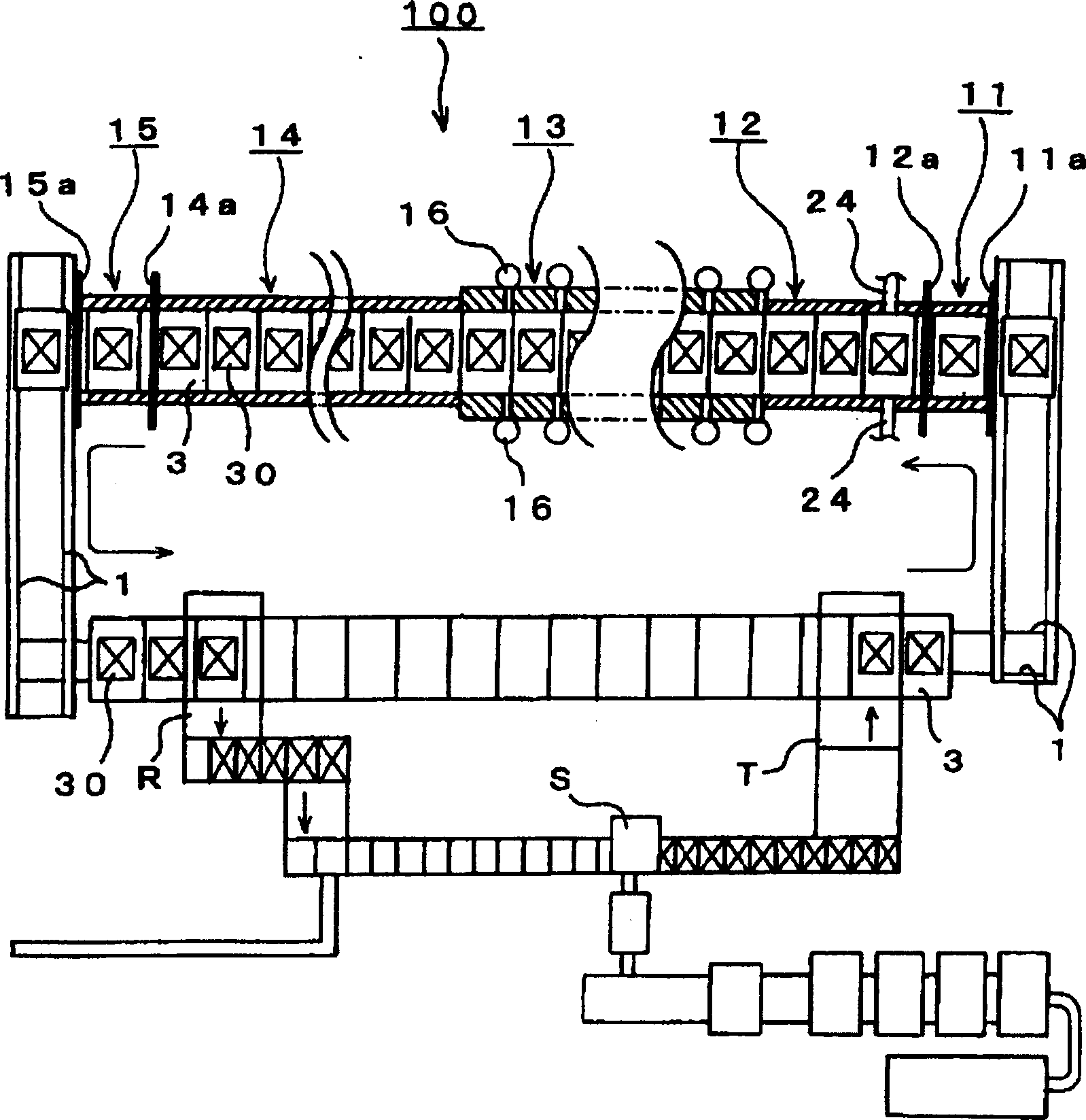
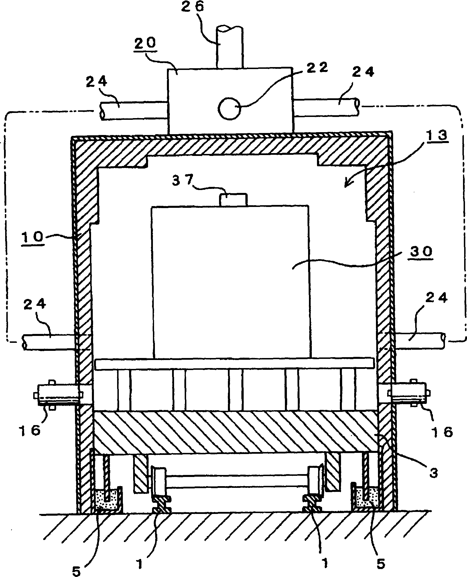
[0088] figure 1 It is a partially disconnected plan view schematically showing the overall view of the continuous carbonization device 100 used for implementing the carbonization method of the present invention, figure 2 It is a longitudinal sectional view of main parts of the tunnel furnace constituting the continuous carbonization apparatus 100 .

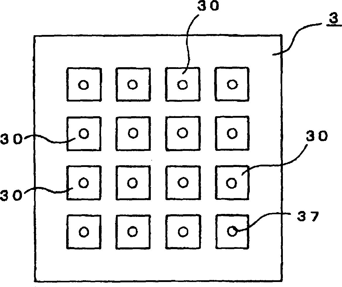
[0089] In the figure, a continuous carbonization device 100 includes a tunnel furnace 10, a reburning deodorization furnace 20 for heat-treating exhaust gas discharged from the tunnel furnace 10; On the trolley 3, a carbonization storage box 30 for storing substances to be carbonized is placed; when t...


PUM


Abstract

The present invention provides one kind one continuous carbonizing method and apparatus. The method can treat great amount of matter without generating offensive odor, and has raised carbonizing efficiency, reduced fuel consumption and lowered cost. The continuous carbonizing apparatus includes long horizontal tunnel kiln comprising preparing zone, pre-heating zone, carbonizing zone, cooling zone and conveying zone successively; and re-burning deodorizing furnace performing heat treatment to gas exhausted from the tunnel kiln. The full carbonizing process from loading the matter to be carbonized into the storing boxes to discharging the carbonized matter is completed in the tunnel kiln.

Description

technical field [0001] The present invention relates to a carbonization method for rapid and continuous carbonization of various wastes including sewer sludge, residual food, animal feces and animal carcasses without generating bad smell, and a continuous carbonization device for implementing the carbonization method. Background technique [0002] This type of carbonization device in the prior art is a stand-alone carbonization device, for example, after pre-drying in a drying furnace to obtain a predetermined moisture content, the dry product is supplied to dry distillation. [0003] In addition, as an apparatus for carbonizing sewage sludge, there is a so-called rotary carbonization apparatus disclosed in Patent Publication (JP-A-11-37645). In this device, the sludge with a moisture content of 75 to 85% is supplied to the drum with several lifting corrugations on the inner wall of the drying furnace, and the sludge is repeatedly lifted from the drum with the lifting corrug...

Claims


Application Information

Patent Timeline
Patent Type & Authority Applications(China)
IPC IPC(8): F23G5/38
Inventor 板津雅春板津孝治板津博之三品仁
Owner C Y C
Why Eureka
Try Eureka