Dustproof film expanding machine

A film expansion machine, dust-proof technology, applied in the field of film expansion machine, can solve problems such as affecting the performance of the machine and accumulating dust on the body

Pending Publication Date: 2021-12-21
江苏昶明智能科技有限公司
View PDF6 Cites 0 Cited by
  • Summary
  • Abstract
  • Description
  • Claims
  • Application Information

AI Technical Summary

Problems solved by technology

[0003] Some existing semi-automatic film expanding machines, in order to facilitate operation, all expose the body used for film expanding on the body. Although this design is easy to operate, it is easy to accumulate dust on the body when not in use. affect machine performance

Method used


Image

  • Dustproof film expanding machine
  • Dustproof film expanding machine
  • Dustproof film expanding machine

Examples


Embodiment 1

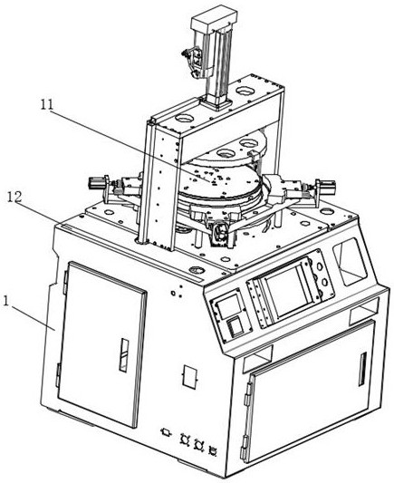
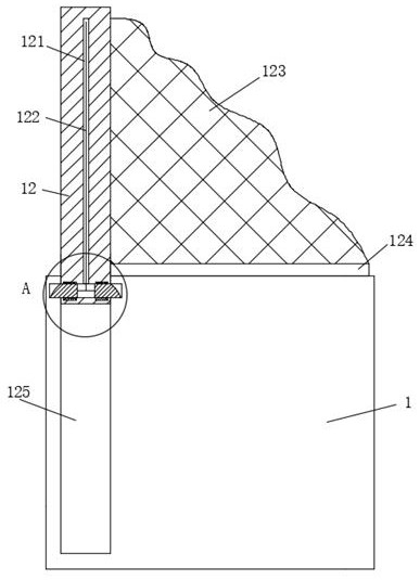
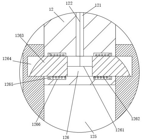
[0033] see Figure 1-5 , a dust-proof film expanding machine, comprising a body 1, a body 11 arranged on the body 1 and in an exposed shape, the body 1 located on one side of the body 11 is provided with a hidden type for the body 11 to prevent The dust-proof mechanism includes a hidden groove 125, a dust-proof plate 12 and a sealing frame 124. The hidden groove 125 is arranged on one side of the fuselage 11; the dust-proof plate 12 can slide up and down. connected in the hidden groove 125; the sealing frame 124 is U-shaped, and the sealing frame 124 is rotatably connected in the dustproof plate 12; wherein, the dustproof plate 12 is provided with a shrinkage groove matching the sealing frame 124 127, the bottom of the sealing frame 124 is rotatably connected with the shrinking groove 127, and a dust cover 123 is connected between the inner wall of the shrinking groove 127 and the frame of the sealing frame 124 and is used for dustproofing of the fuselage 11. The cover 123 is...

Embodiment 2

[0042] The same point with Example 1 is not repeated, and the difference with Example 1 is:

[0043] see Figure 6-7 , the sealing frame 124 includes a horizontal bar and a vertical bar. There are two vertical bars, and the vertical bars are symmetrically distributed at both ends of the horizontal bar. The vertical bars include a first bar 1242 and a second bar 1241. The end of a rod 1242 is provided with a chute 12422 for sliding connection of the second rod 1241, and a second spring 12421 for fixed connection and automatic contraction of the second rod 1241 is provided in the chute 12422. The second spring 12421 It is fixedly connected with the end of the corresponding second rod 1241, the dust cover 123 is fixedly connected with the horizontal rod and the vertical rod, respectively, and the first rod 1242 and the second rod 1241 are both provided with aligned and interconnected squeeze bars. Pressing groove, the cross-section of the pressing groove is convex, the bottom of...


PUM


Abstract

The invention discloses a dustproof film expanding machine, which comprises a body and an exposed machine body arranged on the body, wherein a hidden dustproof mechanism used for preventing dust of the machine body is arranged on the body located on one side of the machine body, the dustproof mechanism comprises a hidden groove, a dustproof plate and a sealing frame, and the hidden groove is formed in one side of the machine body; the dustproof plate is slidably connected into the hidden groove in a vertical moving mode; the sealing frame is in a U shape, and the sealing frame is rotationally connected into the dustproof plate; and a contraction groove matched with the sealing frame is formed in the dustproof plate, the bottom part of the sealing frame is rotationally connected with the contraction groove, a dustproof cover which is connected with the contraction groove and used for preventing dust of the machine body is arranged between the inner wall of the contraction groove and the border of the sealing frame, and the dustproof cover is in a soft and foldable shape. Through the design of the contraction groove, the dustproof cover and the sealing frame, after the dustproof plate is completely pulled out, the sealing frame can rotate outwards to drive the folded dustproof cover to be completely unfolded, so that the dustproof cover completely seals the exposed body, and dust prevention is realized.

Description

technical field [0001] The invention belongs to the technical field of film expanding machines, in particular to a dust-proof film expanding machine. Background technique [0002] In the production process of wafers, processes such as film sticking, laser cutting film, film removal, mold injection, and film expansion are involved. In order to ensure that the dies of the wafer meet the inspection requirements, it is necessary to perform a slicing operation. However, since there are no gaps between the adjacent cores of the wafer, it will cause abnormal problems such as chipping and scratching of adjacent cores during the slicing process, which seriously affects the quality of the wafer and is not conducive to subsequent production needs. . Therefore, it is necessary to perform a film expansion process on the wafer to increase the gap between the die to facilitate the removal of the die. [0003] For some existing semi-automatic film expanding machines, in order to facilita...

Claims


Application Information

Patent Timeline
Patent Type & Authority Applications(China)
IPC IPC(8): H01L21/67B01D46/10
CPCH01L21/67092H01L21/67132B01D46/10
Inventor 安长龙
Owner 江苏昶明智能科技有限公司
Why Eureka
Try Eureka