Shaping method and device for cutting tool

A shaping device and tool technology, applied in the direction of comprehensive factory control, etc., can solve the problems of labor cost, tool not meeting the flatness requirements, time-consuming and other problems, and achieve the effects of saving manpower, improving production efficiency and production accuracy

Active Publication Date: 2021-12-24
TAIYUAN UNIV OF TECH
View PDF6 Cites 1 Cited by
  • Summary
  • Abstract
  • Description
  • Claims
  • Application Information

AI Technical Summary

Problems solved by technology

However, due to heat treatment, grinding and other processes in the manufacturing process of the cutting tools, most of the cutting tools do not meet the flatness requirements, so the flatness testing and shaping are required before the cutting tools leave the factory
The traditional process relies on the naked eye to observe the unevenness and then correct it. This method not only consumes labor costs and time, but also is difficult to ensure sufficient accuracy.

Method used


Image

  • Shaping method and device for cutting tool
  • Shaping method and device for cutting tool
  • Shaping method and device for cutting tool

Examples


Embodiment 1

[0027] This embodiment provides a shaping method for cutting tools. In the finite element software, the standard tool is divided into n rectangular blocks, and the numbers from the handle to the tip or from the tip to the handle are set as 1, 2, 3...n in sequence, Simulate the wide surface and narrow surface of n rectangular blocks respectively, proceeding from 1 to n in sequence, apply several groups of forces from small to large on the wide surface of the first rectangular block, and observe the wide surface of the rectangular block corresponding to each group of forces Generate the size of the plastic deformation, draw a curve of the relationship between force and plastic deformation, repeat n times, and obtain the curve group of the relationship between force and plastic deformation on the wide surface of the standard tool;

[0028] Apply several groups of forces from small to large on the narrow surface of the first rectangular block, observe the size of the plastic deform...

Embodiment 2

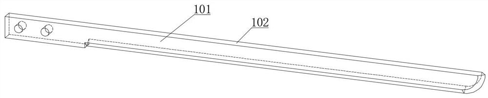
[0033] The cutting tool is 193mm long, 8mm wide, and 2.5mm thick, and is made of M2 high-speed steel. In the finite element software abaqus, the wide surface and narrow surface of the standard tool are divided into 21 rectangular blocks, and the rectangles from the handle to the tip of the tool are called 1, 2, 3...21 for short. First set the force area to 1, and then change the magnitude of the force to obtain a curve named 1, name it wide surface 1 on the wide surface, and name it narrow surface 1 on the narrow surface; then set the force area to 3. Get the curve named 3; repeat the same operation, you can get the curve of the relationship between force and plastic deformation at a specific point on the two surfaces of the tool that need to be shaped.

[0034] The specific method of using Abaqus simulation in this embodiment is:

[0035] 1 Import the artifact;

[0036] 2 Import material properties;

[0037] 3 assembly;

[0038] 4 Determine the analysis step (first step: ...

Embodiment 3

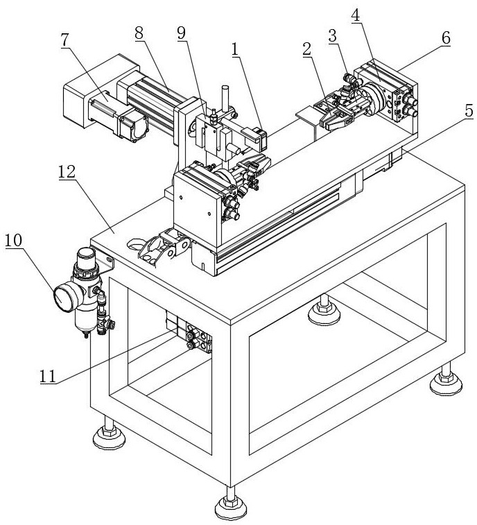
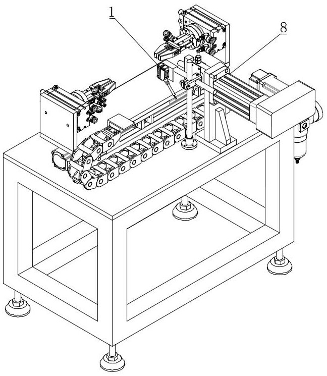
[0048] This embodiment provides a cutting tool shaping device, including a control system, two sets of manipulators for fixing the tip and handle of the knife to be processed, a rotating mechanism connected with the manipulators, and a movable workbench for installing the manipulators and the rotating mechanism And the laser displacement sensor 1 and the force leveling mechanism perpendicular to the tool to be processed; the curve formula in the shaping method of the cutting tool described in embodiment 1 is preset in the control system, and the control system controls the movable work that is loaded with the tool to be processed The table makes reciprocating linear translation along the direction of the tool to be processed, and the size of the plastic deformation of the protrusion on the tool to be processed is detected by the laser displacement sensor 1. When the protrusion is detected by the laser displacement sensor 1, the displacement of the movable worktable determines th...


PUM


Abstract

The invention provides a shaping method and device for a cutting tool, and belongs to the technical field of intelligent numerical control machining of the cutting tool. The method comprises the following steps that firstly, a three-dimensional model of the tool is established, the relation between plastic deformation and stress of different positions of the tool is analyzed through the simulation technology according to a tool material, and then an automatic shaping device for the tool is designed. Deformation detection and shaping tasks of the tool are automatically completed, intelligent automatic control over the shaping process of the cutting tool is achieved, the production efficiency and production precision of shaping of the cutting tool are effectively improved, and manpower is saved.

Description

technical field [0001] The invention belongs to the technical field of intelligent numerical control machining of cutting tools, and specifically discloses a shaping method and device for cutting tools. Background technique [0002] Cutting tools are consumables in the field of garment processing, and are mainly used for cutting and processing of fabrics. After processing a specific cutting tool in a sewing machine factory, there is a final step before leaving the factory: tool shaping. Such as figure 1 , Tool shaping is to ensure the flatness of two wide faces and one narrow face of the tool. However, due to heat treatment, grinding and other processes in the processing and manufacturing process of the cutting tools, most of the cutting tools do not meet the flatness requirements, so the flatness testing and shaping are required before the cutting tools leave the factory. The traditional craft relies on the naked eye to observe the unevenness and then correct it. This me...

Claims


Application Information

Patent Timeline
Patent Type & Authority Applications(China)
IPC IPC(8): B23P6/00
CPCB23P6/00Y02P90/02
Inventor 汪成文刘薏翻
Owner TAIYUAN UNIV OF TECH
Why Eureka
Try Eureka