
Steel pipe polishing and derusting device for bridge construction

A technology for steel pipes and bridges, which is applied in the field of steel pipe grinding and derusting devices for bridge construction, which can solve problems such as equipment jamming, safety failure, and inability to guarantee, achieve efficient positioning and clamping, ensure working environment, and improve practicability Effect

Active Publication Date: 2021-12-24
青海格茫公路管理有限公司
View PDF11 Cites 2 Cited by
  • Summary
  • Abstract
  • Description
  • Claims
  • Application Information

AI Technical Summary

Problems solved by technology

[0005] For construction in the actual saline desert soil environment, the strength and tensile properties of steel pipes need to be improved first, and the anti-corrosion performance of steel pipes must be tested to ensure that the steel pipes will not be corroded and broken during the entire life cycle of the project. problem, but there is no guarantee that there will be no corrosion. The adjustment of the structural strength of the steel pipe requires the production of the steel pipe. In order to meet the design requirements, the inside of the steel pipe often needs to form austenite. When grinding the outer wall of the round pipe, the actual During the production process, the safety is not enough, and the debris splashing on site is relatively serious. After a long time of use, it is easy to generate a large amount of metal debris accumulation, which eventually leads to the problem of equipment jamming. Secondly, in the production process, the clamping of the equipment The work is often clamped and fixed by clamps. When dealing with different steel pipes, the clamps need to be replaced frequently, and the actual production efficiency is low.

Method used


Image

  • Steel pipe polishing and derusting device for bridge construction
  • Steel pipe polishing and derusting device for bridge construction
  • Steel pipe polishing and derusting device for bridge construction

Examples


Embodiment Construction

[0027] In order to make the object, technical solution and advantages of the present invention clearer, the present invention will be further described in detail below in conjunction with the accompanying drawings and embodiments. It should be understood that the specific embodiments described here are only used to explain the present invention, not to limit the present invention.

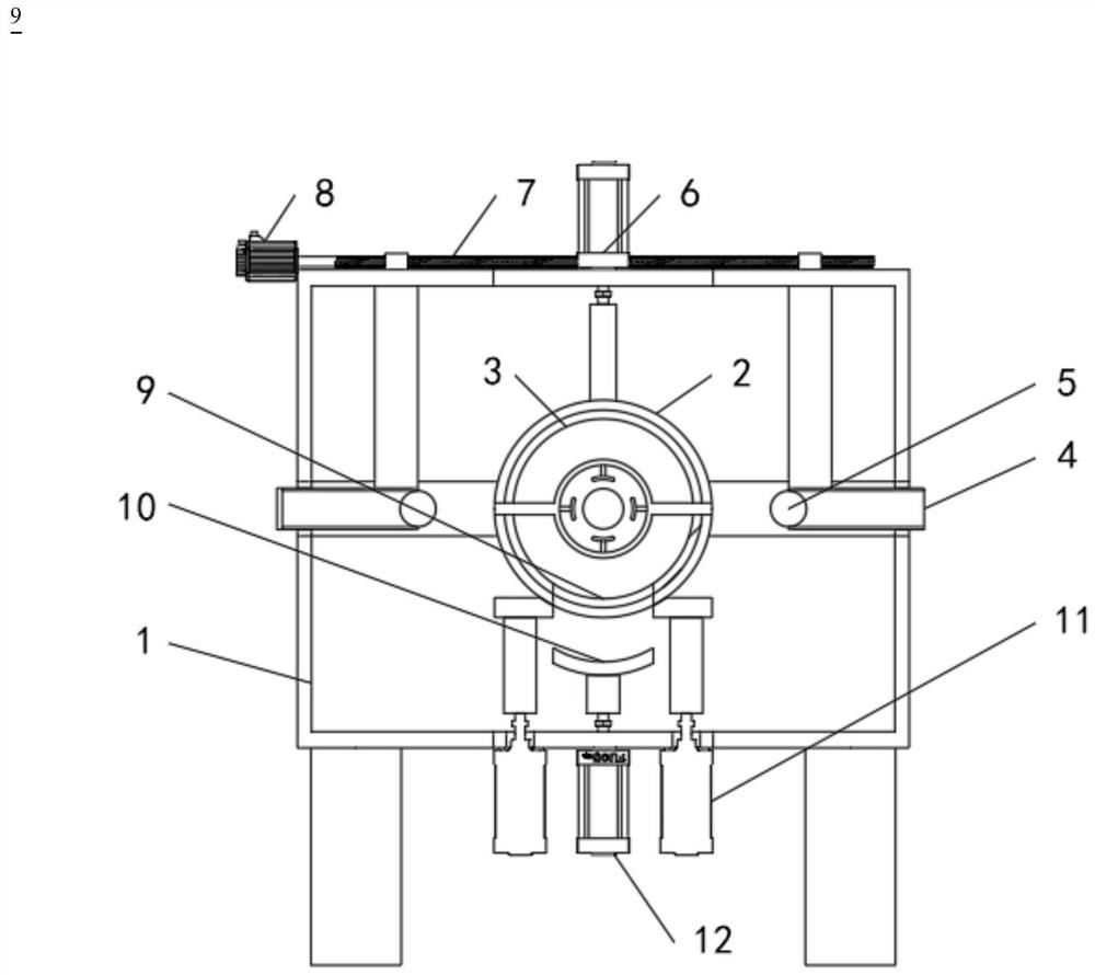
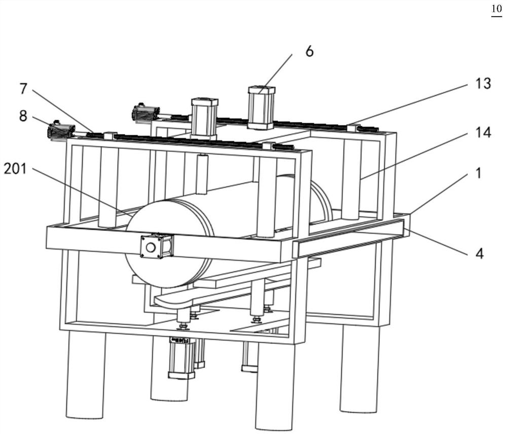
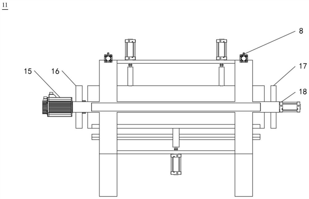
[0028] see Figure 1-6 A steel pipe grinding and derusting device for bridge construction includes a positioning grinding structure and a sealing structure. The positioning grinding structure includes a working frame 1, a limiting frame 4, a grinding cylinder 5, a rotating motor 15, a clamping plate 16, a telescopic plate 17, an extrusion Compression cylinder 18, clamping cylinder 19 and limit plate 21, rotating motor 15 are installed at the center of the outer wall side of the working frame 1 through bolts, and the center of the outer wall side of the clamping plate 16 is fixed at the output of th...


PUM


Abstract

The invention discloses a steel pipe polishing and derusting device for bridge construction. The steel pipe polishing and derusting device comprises a positioning and polishing structure and a sealing structure, the positioning and polishing structure comprises a working frame, a limiting frame, a polishing barrel, a rotating motor, a clamping plate, a telescopic plate, an extrusion air cylinder, a clamping air cylinder and a limiting plate, the rotating motor is installed at the center of one side of the outer wall of the working frame through a bolt, and the center of one side of the outer wall of the clamping plate is fixedly arranged at the output end of the rotating motor. According to the steel pipe polishing and derusting device for bridge construction, efficient positioning and clamping of steel pipes with different pipe diameters can be achieved through the positioning and polishing structure and the sealing structure, in the polishing process, slipping and thread slipping are avoided, eccentric polishing is avoided in the polishing process, and finally the structural strength of steel pipes is not reduced; and in addition, in the polishing and anti-rust paint spraying process, a sealing shell is combined, dust and anti-rust paint generated during rust removal cannot leak into the working environment, so that the working environment of workers is guaranteed, industrial injuries are avoided, and the practicability of the steel pipe polishing and derusting device is improved.

Description

technical field [0001] The invention belongs to the technical field of engineering construction, in particular to a steel pipe grinding and derusting device for bridge construction. Background technique [0002] Highway and bridge construction, often combined with the local construction environment, will use a large number of prefabricated structures, steel pipes and cement. Among them, the treatment of steel pipes will directly affect the progress and quality of the project. [0003] Steel pipes refer to steel materials for concrete-filled steel pipes and prestressed steel pipes for concrete-filled steel pipes. The straight or coiled steel used for reinforcement can be divided into two types: smooth round steel tube and deformed steel tube, and the delivery state is straight and coiled. [0004] With the state's investment in infrastructure construction in the western region in recent years, more and more road construction companies need to overcome the environment in the ...

Claims


Application Information

Patent Timeline
Patent Type & Authority Applications(China)
IPC IPC(8): B24B27/033B24B41/06B24B41/00B24B47/22B24B55/06B24B47/12B05B16/20B05B16/40
CPCB24B27/033B24B41/067B24B41/005B24B47/22B24B55/06B24B47/12B05B16/20B05B16/40
Inventor 马渝翔薛兆锋龚晓琴王维昊王学兰
Owner 青海格茫公路管理有限公司
Learn More