Automatic adhesive tape tearing equipment

A tape and equipment technology, applied in the field of automatic tape tearing equipment, can solve the problems of unfavorable winding process, unfavorable continuous processing, unfavorable accurate positioning and so on

Pending Publication Date: 2021-12-24
苏州鑫本智能科技有限公司
View PDF1 Cites 6 Cited by
  • Summary
  • Abstract
  • Description
  • Claims
  • Application Information

AI Technical Summary

Problems solved by technology

Obviously there is no way to automate the removal
Moreover, based on the material characteristics of the tape/film, the blade is very easy to damage the wound tape/film during the high-speed rotation process, which is extremely unfavorable for the winding process, and it is not conducive to the automatic splicing process
2. Structural transplant coverage, it is difficult to remove tapes in different sticking directions through the arrangement of one side/one side direction
The product needs to be positioned and calibrated during the processing, so that it can be more effective to remove the tape, and it is impossible

Method used


Image

  • Automatic adhesive tape tearing equipment
  • Automatic adhesive tape tearing equipment
  • Automatic adhesive tape tearing equipment

Examples


Embodiment Construction

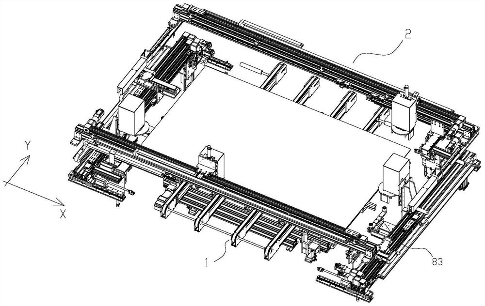
[0036] An automatic tape tearing device is mainly used in the processing of photovoltaic products, especially in conjunction with the automatic production line of photovoltaic products.

[0037] The equipment is structurally carried by the frame 7, and the outside of the frame 7 is a sheet metal outer plate 71. The frame 7 is formed by butting profiles, and can further serve as a bearing basis for a specific structure. Structures such as an industrial control box 72 are also arranged on one side of the frame 7 .

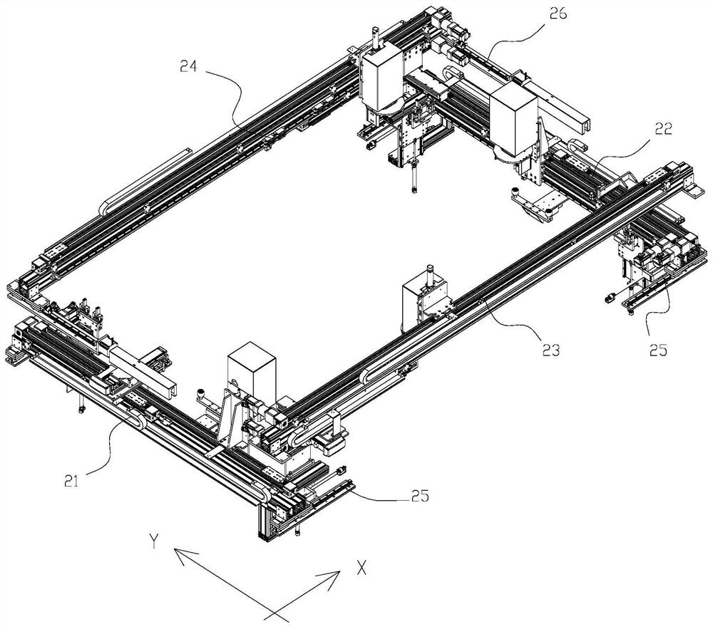
[0038] Based on the loading of the frame 7, the main structure of the equipment includes: a conveying mechanism 1, a transfer mechanism 2, a tape tearing mechanism 3, a receiving mechanism 4, a blanking mechanism 5, a glass lifting mechanism 6, etc. in:

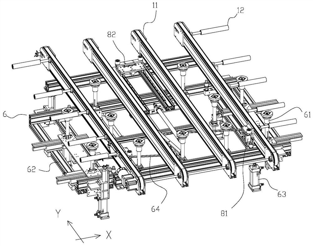
[0039] The conveying mechanism 1 adapts to the assembly line operation in a linear feeding mode; the conveying mechanism 1 includes a plurality of parallel and evenly spaced conveyor belt assemblies 11 arranged si...


PUM


Abstract

The invention discloses automatic adhesive tape tearing equipment which is adapted to the processing process of photovoltaic products. The automatic adhesive tape tearing equipment comprises a conveying mechanism adapted to assembly line work in a linear feeding mode, an adhesive tape tearing mechanism erected on the upper side of the photovoltaic products through a transfer mechanism, a material receiving mechanism and a discharging mechanism; the adhesive tape tearing mechanism can respectively generate displacement actions of tearing an adhesive tape/a covering film in the width and/or length direction of the products; the material receiving mechanism is configured to be a winding structure driven by the transfer mechanism and can wind the torn adhesive tape/covering film while the adhesive tape tearing mechanism acts; and the discharging mechanism comprises a clamping assembly arranged relative to the material receiving mechanism so as to take down the wound adhesive tape/covering film from the material receiving mechanism. According to the equipment and the structure, the automatic implementation and control of the film tearing action are realized, the rhythm of the whole line is improved, the labor cost is reduced, and the efficiency of the whole station is improved.

Description

technical field [0001] The technical field to which the present invention relates, in particular, relates to an automatic tape tearing device suitable for the production and processing of photovoltaic products. Background technique [0002] Compared with the previous production line beat, the current photovoltaic production line has a shorter beat requirement and a higher degree of equipment automation. At present, at each customer site, the tape tearing station is mainly operated manually, which has low efficiency and seriously affects the output of the entire production line. [0003] At this stage, there are also some automatic structures to remove the tape, such as the Chinese utility model patent "Automatic edge tearing equipment for photovoltaic modules", the application number is 202020441219.6. It discloses "comprising a frame body, a corner protection mechanism installed on the frame body, a glue tearing mechanism and a component placement platform, where a photovo...

Claims


Application Information

Patent Timeline
IPC IPC(8): B65B69/00
CPCB65B69/00
Inventor 陈斌徐咏涛
Owner 苏州鑫本智能科技有限公司
Why Eureka
Try Eureka