
Tooling design method

Pending Publication Date: 2021-12-28
东风模具冲压技术有限公司
View PDF0 Cites 0 Cited by
  • Summary
  • Abstract
  • Description
  • Claims
  • Application Information

AI Technical Summary

Problems solved by technology

[0003] 1) The structure design of the existing end picker is based on the stamping process of the parts from scratch, and the design is carried out according to the design standard of the end picker. This design method has long design cycle, low degree of standardization, duplication of some structures, and structural design. Issues such as unreasonable and need to be revised repeatedly;
[0004] 2) It takes a long time: the design of a complete set of end pickers for a part takes an average of 100 hours of design man-hours, scattered in the hands of each designer, and the cycle is at least half a month, which seriously occupies the designer's other mold design time;
[0005] 3) The stamping process of the parts is changed frequently, and the position of the suction cup of the end picker is often changed, which leads to repeated modification and redesign of the designer, which greatly increases the workload of the designer;
[0006] 4) There are many assembly parts: before the standard assembly is developed, a set of end pickers contains dozens of parts;
[0007] 5) The assembly process is complicated: the structural characteristics of the end picker determine that the designer performs a simple and repetitive low-level labor, with many assembly parts and complicated operation steps, especially the design and assembly of the end picker steel pipe takes a lot of time for the designer and energy

Method used


Image

  • Tooling design method
  • Tooling design method
  • Tooling design method

Examples


Embodiment Construction

[0046] The present invention will be further described below in conjunction with the accompanying drawings and specific embodiments.

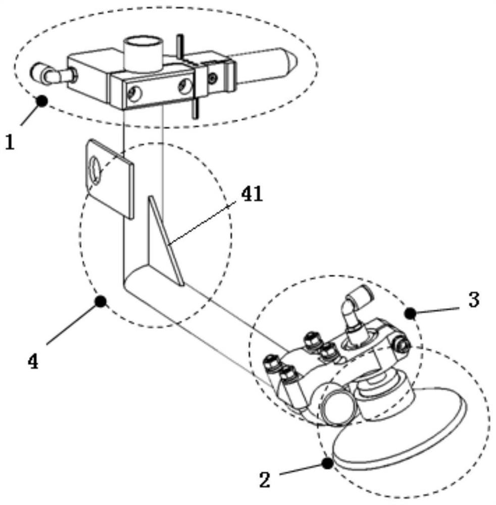
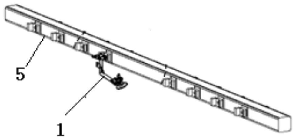
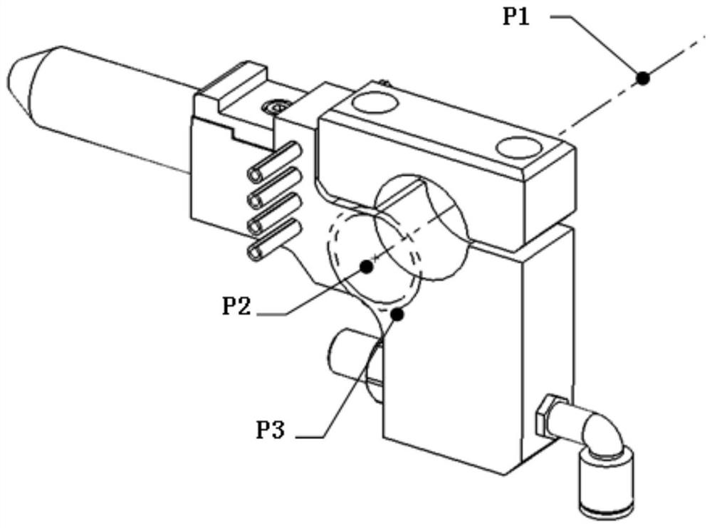
[0047] Such as figure 1 As shown, a complete set of end effector is composed of dozens of parts. According to the function and use of the parts, the end effector is divided into four major parts: bracket assembly 1, suction cup assembly 2, ball shaft assembly 3 and steel pipe Composite 4.

[0048] Such as Figure 2-7 As shown, a method for designing an end picker of the present invention includes the following steps:

[0049] S1, assembly of suction cup assembly 2 and ball shaft assembly 3:

[0050] According to the process part data with the position and size of the suction cup provided by the stamping process, select the arc line of the suction cup and the surface where the arc line is located, extract the center point of the arc and the normal vector of the surface passing through the center point, and assemble the suction cup assembly 2 ...


PUM


Abstract

The invention relates to a tooling design method. The method comprises the following steps: S1, assembling a suction cup assembly and a ball shaft assembly; S2, assembling a cross beam assembly and a support assembly; and S3, designing a steel pipe assembly. The ball shaft assembly assembled in step S1 and the support assembly assembled in step S2 are selected, parameters needed by the steel pipe assembly are obtained, the variable-parameter steel pipe assembly is assembled into the ball shaft assembly and the support assembly, and the parameters of the steel pipe assembly are updated. Compared with an existing method, the tooling design method has the advantages that the time is shortened by about 3 / 4, repeated labor is reduced, a tooling can be repeatedly used, the design period of the tooling is greatly shortened, the design error of the tooling is reduced, the design standardization of the tooling is improved, and the design and manufacturing cost of the tooling is reduced.

Description

technical field [0001] The invention relates to a design of an automobile stamping die, in particular to an interactive end picker design method. Background technique [0002] With the rapid development of high-speed automated stamping lines in the domestic auto parts stamping industry, the requirements for mold automation are getting higher and higher. As a conveying tool for high-speed automated stamping lines, end pickers are more and more widely used. The existing end pickers basically stay in the stage of manual design, and there are the following problems: [0003] 1) The structure design of the existing end picker is based on the stamping process of the parts from scratch, and the design is carried out according to the design standard of the end picker. This design method has long design cycle, low degree of standardization, duplication of some structures, and structural design. Issues such as unreasonable and need to be revised repeatedly; [0004] 2) It takes a lo...

Claims


Application Information

Patent Timeline
Patent Type & Authority Applications(China)
IPC IPC(8): G06F30/17G06F30/20
CPCG06F30/17G06F30/20
Inventor 胡海周晓娟
Owner 东风模具冲压技术有限公司
Learn More