
Method and device for calculating bolt stress caused by additional torque and storage medium

A bolt stress and calculation method technology, applied in special data processing applications, instruments, electrical digital data processing, etc., can solve problems such as bolt stress relaxation, bolt stress and fatigue results increase, failure, etc., to achieve strong guidance and improve Stability and the effect of reducing the risk of equipment operation

Pending Publication Date: 2021-12-28
HARBIN ELECTRIC POWER GENERATION EQUIP NAT ENG RES CENT CO LTD
View PDF0 Cites 0 Cited by
  • Summary
  • Abstract
  • Description
  • Claims
  • Application Information

AI Technical Summary

Problems solved by technology

One of the in-service defects of petrochemical containers and large steel structures is bolt defects, including thread defects, reduction of bolt pre-tightening force, bolt stress relaxation, and bolt fracture. The stress and fatigue of the bolts will increase and eventually fail, which will seriously affect the normal and safe operation of the equipment
[0004] At present, there is no more accurate theoretical calculation method for the anchor bolts of petrochemical containers and large steel structures. Most of them are based on estimation or rough calculation. On land, on the hull, or installed on a car or train, it will be subjected to additional moments generated by earthquakes, waves, emergency braking, shaking, etc., often breaking its bolts and causing damage.
[0005] Therefore, there is an urgent need for a bolt stress calculation method to solve the problem that there is no accurate calculation method for the anchor bolts of petrochemical containers and large steel structures, which will lead to increased bolt stress and fatigue strength of the equipment, and eventually fail, affecting the normal and safe operation of the equipment. The problem

Method used


Image

  • Method and device for calculating bolt stress caused by additional torque and storage medium
  • Method and device for calculating bolt stress caused by additional torque and storage medium
  • Method and device for calculating bolt stress caused by additional torque and storage medium

Examples


specific Embodiment approach 1

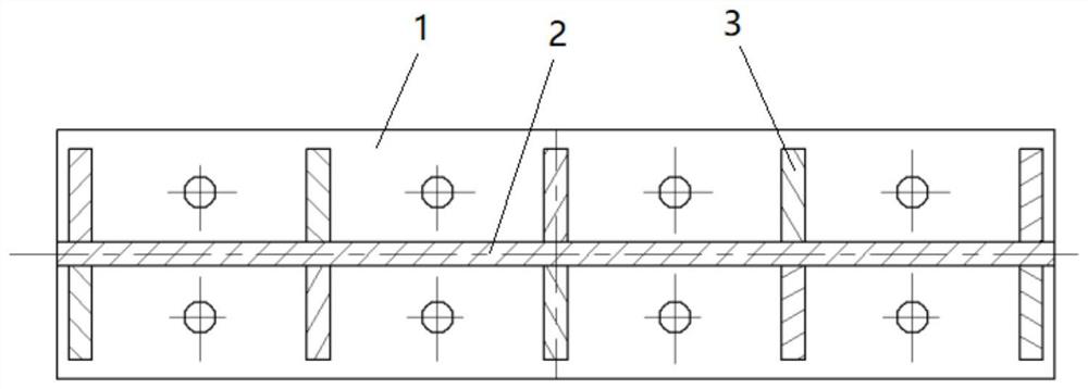
[0057] combine figure 1 and figure 2 As shown, this embodiment provides a method for calculating the bolt stress caused by the additional moment, aiming at the calculation of the bolt stress realized by the saddle support. The saddle support includes a base 1, a web 2 and a rib 3. There is a web 2 running through it horizontally, and the web 2 is vertically arranged with the base 1. There are a plurality of ribs 3 evenly distributed on both sides of the web 2, and a plurality of through holes for bolt installation are processed on the base 1, including the following step:

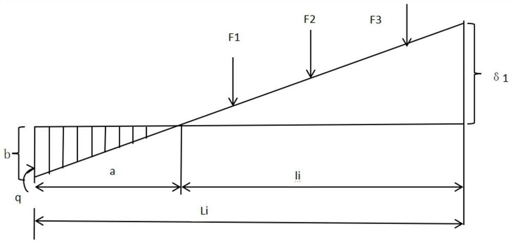
[0058] Step S100, using the principle of similar triangles to obtain the ratio of the deformation δi under the i-th bolt load, the distance li from the center to the i-th bolt load, the distance a from the compression bolt to the center hole, and the axial deformation b of the compression bolt relation:

[0059]

[0060]Step S200: Substituting the distance li from the center to the i-th bolt load, th...

specific Embodiment approach 2

[0107] This embodiment proposes an example of bolt force analysis of saddle supports, and calculates the bolt stresses according to the method of specific embodiment 1, so as to check the effectiveness of this method in the calculation of the bolt stress of saddle supports for petrochemical containers and large steel structures. feasibility.

[0108] 1. Set load data

[0109] Axial force in X direction Fx=45919.6N

[0110] Axial force in Y direction Fy=21944.0N

[0111] Axial force in Z direction Fz=57135.1N

[0112] X direction axial moment Mx=55075222.1N mm

[0113] Axial moment in Y direction My=1245000N·mm

[0114] Axial moment in Z direction Mz=42528316.5N mm

[0115]

[0116] 2. Tensile stress

[0117] Design working condition stress value:

[0118]

[0119] 3. Shear stress

[0120] Design working condition stress value:

[0121]

[0122]

[0123] 4. Calculate the tensile stress generated by My:

[0124]

[0125] Base plate compression length:

...

specific Embodiment approach 3

[0145] Those skilled in the art may use the methods mentioned in the above embodiments, and this embodiment may be provided as a method, a system, or a computer program product. Therefore, the present application may take the form of a complete hardware embodiment, a complete software embodiment, or a combination of software and hardware, and the modules may also be reorganized according to the computer logic structure. Furthermore, the embodiments may take the form of a computer program product embodied on one or more computer-usable storage media (including but not limited to disk storage, CD-ROM, optical storage, etc.) having computer-usable program code embodied therein.


PUM


Abstract

The invention discloses a method and device for calculating bolt stress caused by additional torque and a storage medium, and belongs to the technical field of bolt stress calculation. The method comprises the following steps: step S100, adopting a similar triangle principle to obtain the deformation under an ith bolt load, the distance from the center to the ith bolt load, the distance from a compression bolt to a center hole and the ratio relation of the axial deformation of the compression bolt; step S200, substituting the relationship among the distance from the center to the ith bolt load, the distance Li between the bolt holes on the two sides and the distance a from the compression bolt to the center hole into the relational expression in the step S100, and performing corresponding transformation to obtain the deformation under the ith bolt load; step S300, solving a quadratic equation of one unknown about the distance a from the compression bolt to the center hole; step S400, solving the maximum load of the bolt; and step S500, solving the stress value of the bolt by using a tensile stress calculation formula. The method provided by the invention has strong guidance and is suitable for popularization and application.

Description

technical field [0001] The invention relates to a bolt stress calculation method, equipment and storage medium caused by additional torque, and belongs to the technical field of bolt stress calculation. Background technique [0002] Petrochemical container is the abbreviation of petroleum and chemical equipment, which refers to the general term of equipment used in a series of processes from oil drilling to transportation to processing into chemical products. It mainly includes static equipment including tower equipment, heat exchangers, reactors, storage tanks and various shell equipment and dynamic equipment for conveying media. [0003] Petrochemical containers and large steel structures are mainly installed and fixed by anchor bolts. One of the in-service defects of petrochemical containers and large steel structures is bolt defects, including thread defects, reduction of bolt pre-tightening force, bolt stress relaxation, and bolt fracture. The stress and fatigue of th...

Claims


Application Information

Patent Timeline
Patent Type & Authority Applications(China)
IPC IPC(8): G06F30/17G06F119/14
CPCG06F30/17G06F2119/14Y02T90/00
Inventor 牟力波王凤君邱砚明徐树林范业娇刘艳鹏
Owner HARBIN ELECTRIC POWER GENERATION EQUIP NAT ENG RES CENT CO LTD
Learn More