
Thermal power generation system capable of automatically adjusting output frequency

An output frequency, automatic adjustment technology, applied in the direction of adjusting fuel supply, steam generation method using pressure combustion, electromechanical devices, etc., can solve problems affecting combustion efficiency, generator frequency fluctuation, generator speed fluctuation, etc. Burning effect, mitigating slight fluctuations, prolonging service life

Inactive Publication Date: 2021-12-28
祝嘉薇
View PDF0 Cites 0 Cited by
  • Summary
  • Abstract
  • Description
  • Claims
  • Application Information

AI Technical Summary

Problems solved by technology

[0002] Thermal power generation is a power generation method that uses the heat generated by combustibles during combustion and converts it into electrical energy through a power generation device. However, combustion is a complex chemical reaction, which leads to the fact that even if a fixed supply of oxygen and fuel is guaranteed It is difficult to ensure that the amount of steam generated is consistent, and when the pulverized coal used in the combustion process is injected into the combustion chamber, because the distance between the pulverized coal is too close, the contact with oxygen is insufficient, which affects the combustion efficiency, which in turn leads to The rotation speed of the generator fluctuates, and the fluctuation of the rotation speed will lead to the fluctuation of the generator frequency. If the frequency is too high or too low, it will affect the service life of the generator. However, the existing adjustment of the generator speed is only for the situation of large fluctuations. A device for fine-tuning the steam pressure to the combustion situation

Method used


Image

  • Thermal power generation system capable of automatically adjusting output frequency
  • Thermal power generation system capable of automatically adjusting output frequency
  • Thermal power generation system capable of automatically adjusting output frequency

Examples


Embodiment Construction

[0019] In order to make the purpose and advantages of the present invention clearer, the present invention will be described in detail below in conjunction with the embodiments. It should be understood that the following words are only used to describe a thermal power generation system or several specific implementations of the present invention that automatically adjusts the output frequency manner, without strictly limiting the scope of protection specifically claimed by the present invention, as used herein, the terms up and down and left and right are not limited to their strict geometric definitions, but include reasonable and inconsistent tolerances for machining or human error , the specific features of this thermal power generation system that automatically adjusts the output frequency are described in detail below:

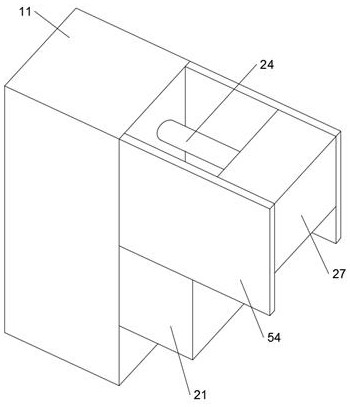
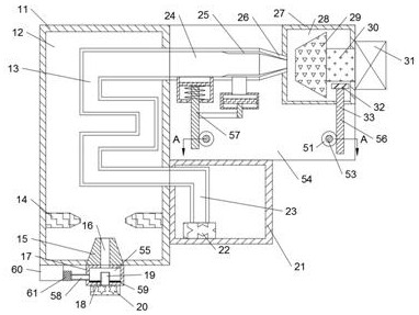
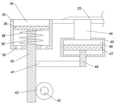
[0020] With reference to the accompanying drawings, a thermal power generation system that automatically adjusts the output frequency according to an embo...


PUM


Abstract

A thermal power generation system capable of automatically adjusting the output frequency is disclosed in the invention, and comprises a combustion chamber, a combustion cavity is formed in the combustion chamber, and a pulverized coal box is fixedly arranged on the lower end face of the combustion chamber; the size of the opening of a steam nozzle is adjusted by sensing the steam pressure, the fine adjustment effect on the steam pressure is achieved, slight fluctuation caused by combustion is relieved, the service life of a generator is prolonged, and compared with the traditional operation of directly spraying pulverized coal into a combustion chamber, the pulverized coal is adsorbed through air pressure according to the Bernoulli principle, a certain gap is guaranteed between pulverized coal, and the pulverized coal can make full contact with oxygen, so the combustion effect is improved; and through a friction block, when abnormal combustion occurs and the rotating speed of the generator cannot be changed through fine adjustment, the friction block is directly extruded on the power generation shaft, and the generator is prevented from being damaged due to the too high rotating speed.

Description

technical field [0001] The invention relates to the technical field of thermal power generation, in particular to a thermal power generation system that automatically adjusts output frequency. Background technique [0002] Thermal power generation is a power generation method that uses the heat generated by combustibles during combustion and converts it into electrical energy through a power generation device. However, combustion is a complex chemical reaction, which leads to the fact that even if a fixed supply of oxygen and fuel is guaranteed It is difficult to ensure that the amount of steam generated is consistent, and when the pulverized coal used in the combustion process is injected into the combustion chamber, because the distance between the pulverized coal is too close, the contact with oxygen is insufficient, which affects the combustion efficiency, which in turn leads to The rotation speed of the generator fluctuates, and the fluctuation of the rotation speed wil...

Claims


Application Information

Patent Timeline
Patent Type & Authority Applications(China)
IPC IPC(8): H02J3/24H02K7/18F01D15/10F01D17/14F01D17/26F01D21/00F01D21/14F22B1/22F22B33/18F23K3/02F23N1/00
CPCH02J3/24H02K7/1807F01D17/14F01D17/26F01D15/10F01D21/006F01D21/14F22B1/22F22B33/18F23K3/02F23N1/007
Inventor 祝嘉薇
Owner 祝嘉薇
Features
  • Generate Ideas
  • Intellectual Property
  • Life Sciences
  • Materials
  • Tech Scout
  • Unparalleled Data Quality
  • Higher Quality Content
  • 60% Fewer Hallucinations
Learn More