
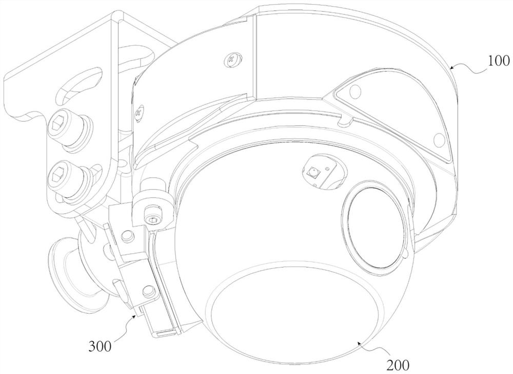
Mining pan-tilt camera

A camera and cloud platform technology, applied in image communication, cleaning methods and appliances, chemical instruments and methods, etc., can solve problems such as poor coordination between brushes and lenses, insufficient light, small lenses, etc., to reduce volume and weight , Improve sealing performance, easy to disassemble and maintain

Pending Publication Date: 2021-12-28
TIANJIN HUANING ELECTRONICS
View PDF0 Cites 1 Cited by
  • Summary
  • Abstract
  • Description
  • Claims
  • Application Information

AI Technical Summary

Problems solved by technology

First of all, in order to meet the requirements of intrinsic safety in the harsh environment, the monitoring equipment in the mine cannot use transparent plastic shells. Both the main body and the pan / tilt need to use all-metal shells. The lens in the metal pan / tilt is shot through the window opened on the pan / tilt shell , the viewing angle of the lens will be limited by the size of the window and the distance between the two. The larger the distance between the two and the smaller the size of the window, the smaller the viewing angle of the lens; but the size of the window itself is also limited by the size of the gimbal. In order to control The size and weight of the overall device often requires sacrificing a certain viewing angle
Secondly, the existing underground monitoring equipment cannot effectively overcome the problem of coal dust covering the lens. Due to the harsh environment of coal mines, large coal dust, and insufficient light, the lens is easily covered by coal dust accumulation when the camera is used in the working face. , reduce the picture quality or even completely lose the monitoring picture, so it needs to be cleaned in time, and the monitoring equipment is often set at a high place, so it is difficult to clean. Some existing cameras with self-cleaning function set a brush next to the pan / tilt, and the pan / tilt When rotating, the brush scrapes off the soot on the lens, the coordination between the brush and the lens is poor, and the cleaning effect is not ideal

Method used


Image

  • Mining pan-tilt camera
  • Mining pan-tilt camera
  • Mining pan-tilt camera

Examples


Embodiment Construction

[0025] The present invention will be described in further detail below in conjunction with specific examples. It should be understood that the specific embodiments described here are only used to explain the present invention, not to limit the present invention.

[0026] In describing the present invention, it should be understood that the terms "center", "longitudinal", "transverse", "upper", "lower", "front", "rear", "left", "right", " The orientations or positional relationships indicated by "vertical", "horizontal", "top", "bottom", "inner" and "outer" are based on the orientations or positional relationships shown in the drawings, and are only for the convenience of describing the present invention and Simplified descriptions, rather than indicating or implying that the device or element referred to must have a particular orientation, be constructed and operate in a particular orientation, and thus should not be construed as limiting the invention.

[0027] In the descri...


PUM


Abstract

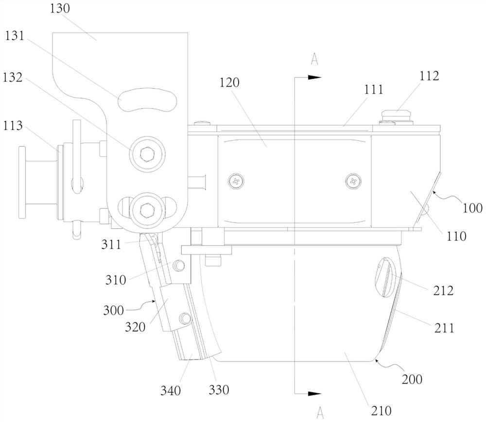
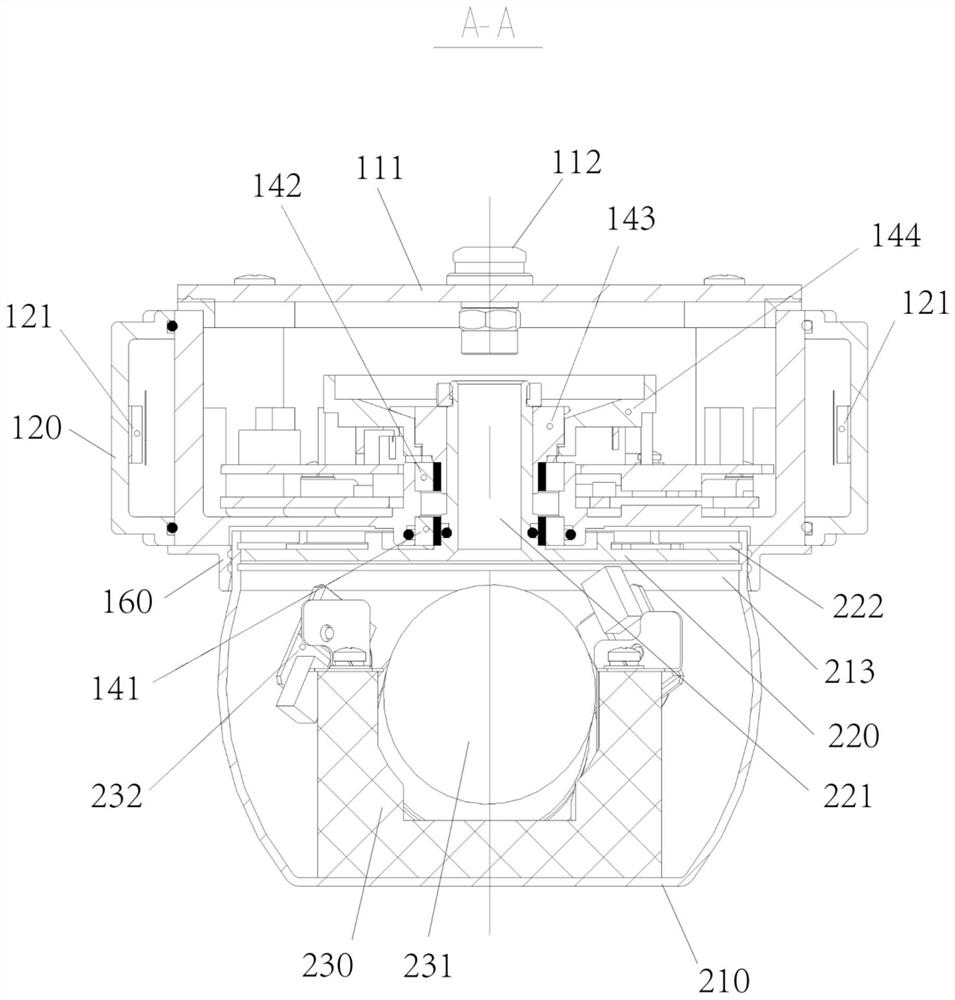
The invention discloses a mining pan-tilt camera which comprises a main machine body, a pan-tilt mechanism and a windscreen wiper mechanism, the top of the pan-tilt mechanism and the top of the windscreen wiper mechanism are both arranged on the lower side of the main machine body, and a scraping strip on the inner side of the windscreen wiper mechanism makes linear contact with the side face of the pan-tilt mechanism; the pan-tilt mechanism comprises a lens spherical shell and a lens assembly arranged in the lens spherical shell, a lens hole is formed in one side of the lens spherical shell, and the lens assembly comprises a zoom lens, a lens base arranged at the bottom of the lens spherical shell and a lens cover embedded in the lens hole. The front part of the lens cover is provided with a glass window, the rear part of the lens cover is connected with the zoom lens, and the tail part of the zoom lens is connected with the lens base. Through the design of the lens assembly, in the limited space of the lens spherical shell, sealing installation of the zoom lens tightly attached to the window is achieved, the lens cover and the window are flush with the surface of the lens spherical shell, and the size and the weight of the whole machine are reduced under the condition that the visual angle is guaranteed.

Description

technical field [0001] The invention relates to the field of monitoring camera equipment, in particular to a mining pan-tilt camera. Background technique [0002] At present, the mode of setting monitoring camera equipment is usually adopted to realize real-time monitoring under the mine, but there are many deficiencies in the existing mine camera monitoring equipment. First of all, in order to meet the requirements of intrinsic safety in the harsh environment, the monitoring equipment in the mine cannot use transparent plastic shells. Both the main body and the pan / tilt need to use all-metal shells. The lens in the metal pan / tilt is shot through the window opened on the pan / tilt shell , the viewing angle of the lens will be limited by the size of the window and the distance between the two. The larger the distance between the two and the smaller the size of the window, the smaller the viewing angle of the lens; but the size of the window itself is also limited by the size o...

Claims


Application Information

Patent Timeline
Patent Type & Authority Applications(China)
IPC IPC(8): H04N5/225B08B1/02
CPCH04N23/51H04N23/50B08B1/165B08B1/20
Inventor 张耀军刘锋李军李姗
Owner TIANJIN HUANING ELECTRONICS
Learn More