Deposition device system
A deposition device and deposition material technology, which are applied in spraying devices, vacuum evaporation plating, coating and other directions, can solve the problems of increased evaporation, disconnection of the first heater, difficulty in preliminary detection of nozzle clogging, and the like. The effect of preventing clogging, reducing cost and maintaining quality
- Summary
- Abstract
- Description
- Claims
- Application Information
AI Technical Summary
Problems solved by technology
Method used
Image

Examples
Embodiment Construction
[0044] Hereinafter, embodiments of the present invention will be described in detail with reference to the accompanying drawings.
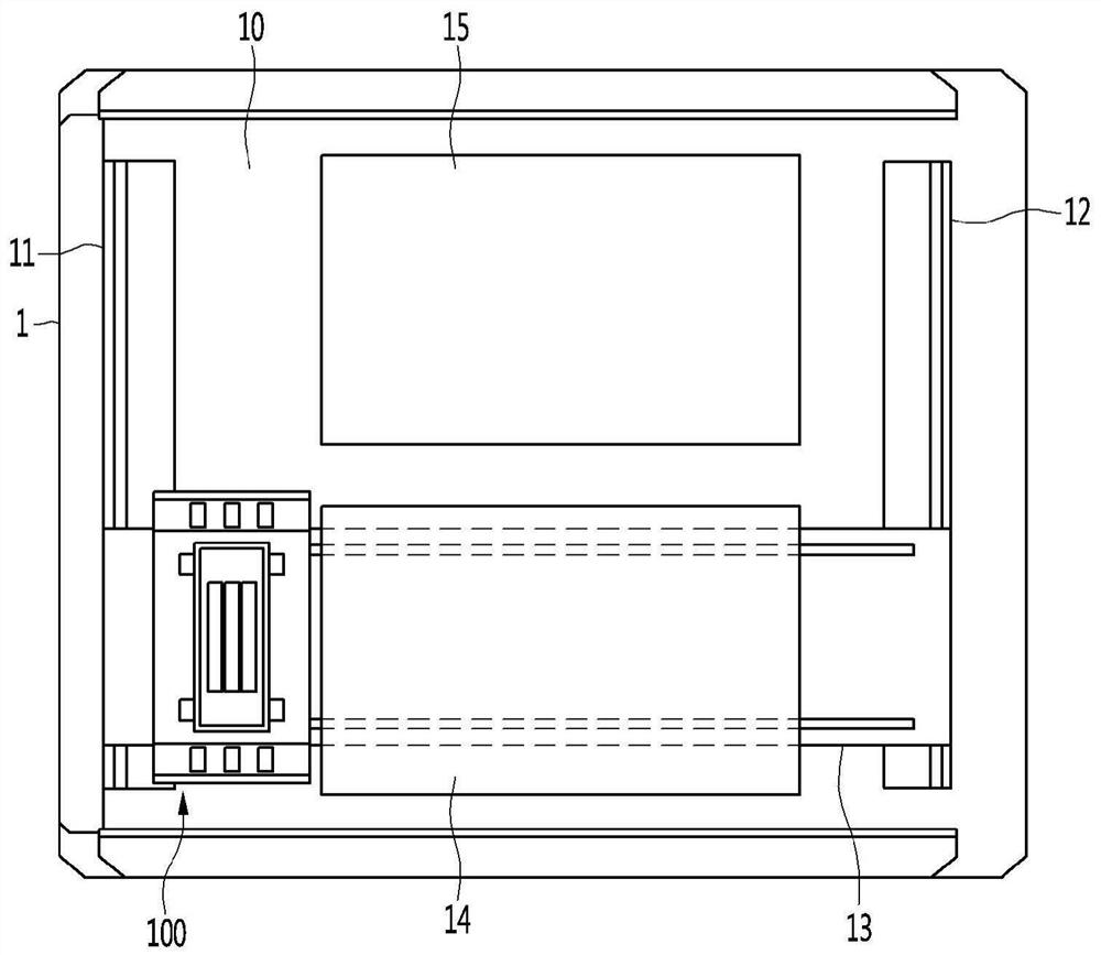
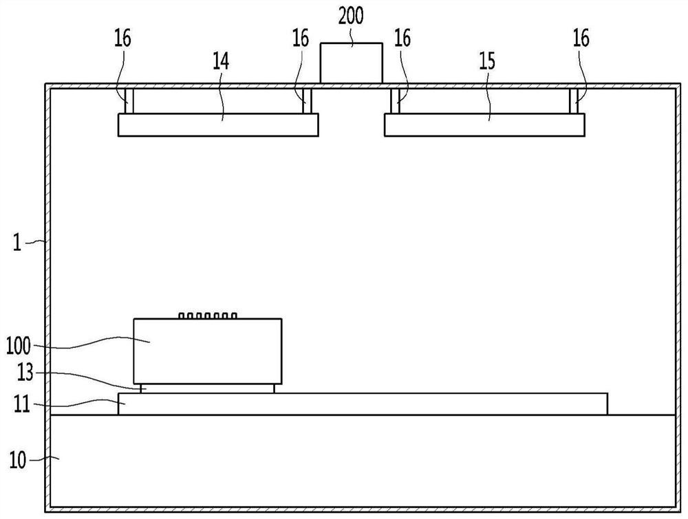
[0045] figure 1 and figure 2 is a diagram schematically showing the inside of the vacuum chamber of the deposition apparatus system according to the embodiment of the present invention when viewed from above and from the front.
[0046] The deposition device system of the embodiment of the present invention may include a vacuum chamber 1, a deposition device 100 movably installed in the vacuum chamber 1, and a clogging detection and removal module 200 detachably arranged on the upper side of the vacuum chamber 1, such as figure 1 and 2 shown.
[0047] The support part 10 is provided on the lower side inside the vacuum chamber 1, the first drive part 11 and the second drive part 12 are arranged side by side in the front-rear direction on both sides on the support part 10, and the third drive part 13 is arranged on both sides. The direction is ...
PUM
 Abstract
Description
Claims
Application Information
 - Generate Ideas
- Intellectual Property
- Life Sciences
- Materials
- Tech Scout
- Unparalleled Data Quality
- Higher Quality Content
- 60% Fewer Hallucinations
Browse by: Latest US Patents, China's latest patents, Technical Efficacy Thesaurus, Application Domain, Technology Topic, Popular Technical Reports.
© 2025 PatSnap. All rights reserved.Legal|Privacy policy|Modern Slavery Act Transparency Statement|Sitemap|About US| Contact US: help@patsnap.com