Supercharge Your Innovation With Domain-Expert AI Agents!

Fixing method for to-be-welded part suitable for linear friction welding

A linear friction welding and fixing method technology, applied in welding equipment, non-electric welding equipment, metal processing equipment, etc., can solve the problems of compression deformation of the parts to be welded, high processing precision of the clamping table, and large processing workload, etc., to achieve The effect of reducing the size of the clamping table, improving efficiency and reducing processing costs

Active Publication Date: 2021-12-31
AVIC BEIJING AERONAUTICAL MFG TECH RES INST
View PDF8 Cites 2 Cited by
  • Summary
  • Abstract
  • Description
  • Claims
  • Application Information

AI Technical Summary

Problems solved by technology

[0004] During the welding process, the welding load is very large, and the load includes the welding force in the vertical direction (vibration direction) and the upsetting force in the horizontal direction (upsetting direction). Fixed, currently commonly used fixed methods such as Figure 4 As shown, the fixture support surface of the plate-shaped part is in contact with the tooling fixture. When the end face of the welding table of the plate-shaped part is subjected to the upsetting force, the tooling fixture supports the plate-shaped part, and the upsetting force is finally transmitted to the fixture; The downward clamping force is applied in the fixture to securely fix the plate-shaped parts in the vertical direction to resist the welding force. However, the structure of the clamping table and the fixing method of the fixture have compression deformation and generation of welded parts. The problem of internal stress, the large size of the clamping table of the parts to be welded, the problem of waste of materials, the high machining accuracy and the large processing workload of the clamping table of the parts to be welded

Method used


Image

  • Fixing method for to-be-welded part suitable for linear friction welding
  • Fixing method for to-be-welded part suitable for linear friction welding
  • Fixing method for to-be-welded part suitable for linear friction welding

Examples


Embodiment Construction

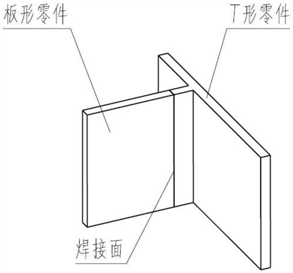
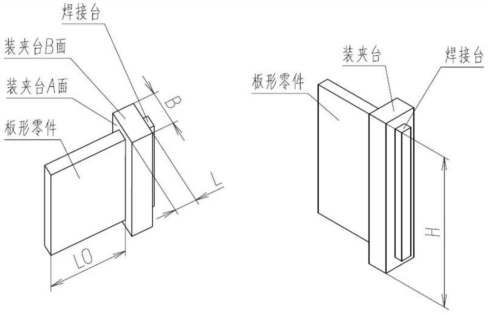
[0036] Embodiments of the present invention will be further described in detail below in conjunction with the accompanying drawings and examples. The detailed description and accompanying drawings of the following embodiments are used to illustrate the principles of the present invention, but cannot be used to limit the scope of the present invention, that is, the present invention is not limited to the described embodiments, without departing from the spirit of the present invention Any modification, substitution and improvement of parts, components and connection methods are covered under.

[0037] It should be noted that, in the case of no conflict, the embodiments in the present application and the features in the embodiments can be combined with each other. The present application will be described in detail below with reference to the accompanying drawings and embodiments.

[0038] Figure 5 It is a structural schematic diagram of an inventive part to be welded according...


PUM


Abstract

The invention relates to a fixing method for a to-be-welded part suitable for linear friction welding. The method comprises the following steps that firstly, a clamping table of the to-be-welded part is processed according to the structure of a target part, and a plurality of mounting holes are symmetrically processed in two side surfaces of the clamping table; secondly, tool clamps matched with the clamping table are machined according to the appearance of the clamping table, and a plurality of spherical protrusions matched with the mounting holes are machined on the tool clamps; and thirdly, the tool clamps are assembled at the two sides of the to-be-welded part, after the spherical protrusions and the mounting holes are correspondingly assembled, the to-be-welded part is fixed between the two tool clamps through screws, multiple mounting holes machined in the to-be-welded part are matched with the corresponding spherical protrusions machined on the tool clamps, the to-be-welded part is fixed, deflection of the to-be-welded part in the welding process can be prevented, it is guaranteed that welding force and upsetting force of the to-be-welded part in the welding process are both borne by the spherical protrusions, and therefore no compressive deformation and no compressive stress of the to-be-welded part can be achieved.

Description

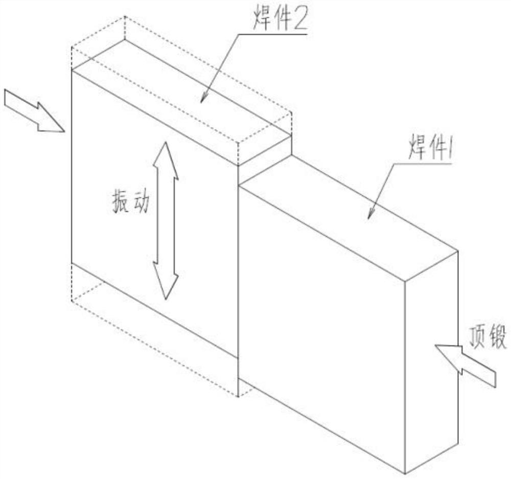
technical field [0001] The invention relates to the field of welding technology, in particular to a method for fixing parts to be welded suitable for linear friction welding. Background technique [0002] Linear friction welding (Linear Friction Welding) is a welding method that has been developed rapidly in recent years. It is mainly used in the manufacture of titanium alloy parts. For its welding principle, see figure 1 , weldment 2 achieves linear vibration with a certain frequency and amplitude in the vertical direction; weldment 1 contacts with the end surface of weldment 2 under the action of upsetting force in the horizontal direction, and high-frequency friction occurs on the contact surface to generate heat. As the temperature rises, the material on the contact surface softens and is extruded. When the extrusion reaches a certain level, the vibration is stopped quickly, and the upsetting force is applied to connect the two weldments as a whole to complete the weldin...

Claims


Application Information

Patent Timeline
Patent Type & Authority Applications(China)
IPC IPC(8): B23K20/12B23K20/26
CPCB23K20/122B23K20/26
Inventor 李辉李菊刘建军
Owner AVIC BEIJING AERONAUTICAL MFG TECH RES INST
Features
  • R&D
  • Intellectual Property
  • Life Sciences
  • Materials
  • Tech Scout
  • Unparalleled Data Quality
  • Higher Quality Content
  • 60% Fewer Hallucinations
Learn More