Conveying line roller capable of limiting driving force

A conveying line and driving force technology, which is applied in the directions of conveyor objects, rollers, transportation and packaging, etc., can solve the problems of heavy workload, attenuation of spring force, and heavy burden of conveying line maintenance, to simplify the mechanism and simplify the transmission. mechanism, the effect of reducing the intensity of maintenance work and the cost of use

Active Publication Date: 2021-12-31
CHINA FIRST AUTOMOBILE +1
View PDF5 Cites 0 Cited by
  • Summary
  • Abstract
  • Description
  • Claims
  • Application Information

AI Technical Summary

Problems solved by technology

Since the friction plate will gradually wear out during use, and the spring force will also attenuate, so the spring pressure needs to be adjusted regularly when using this kind of transmission device. The friction plate wears to a certain extent and needs to be replaced. The workload is huge, resulting in a heavy burden on the maintenance of the conveyor line.

Method used


Image

  • Conveying line roller capable of limiting driving force
  • Conveying line roller capable of limiting driving force
  • Conveying line roller capable of limiting driving force

Examples


specific Embodiment approach

[0027] In order to clearly and completely describe the technical solution of the present invention and its specific working process, in conjunction with the accompanying drawings, the specific implementation of the present invention is as follows:

[0028] In the present invention, unless otherwise clearly specified and limited, terms such as "installation", "connection", "connection" and "fixation" should be understood in a broad sense, for example, it can be a fixed connection or a detachable connection , or integrated; it may be mechanically connected or electrically connected; it may be directly connected or indirectly connected through an intermediary, and it may be the internal communication of two components or the interaction relationship between two components, unless otherwise specified limit. Those of ordinary skill in the art can understand the specific meanings of the above terms in the present invention according to specific situations.

[0029] In the present i...

Embodiment 1

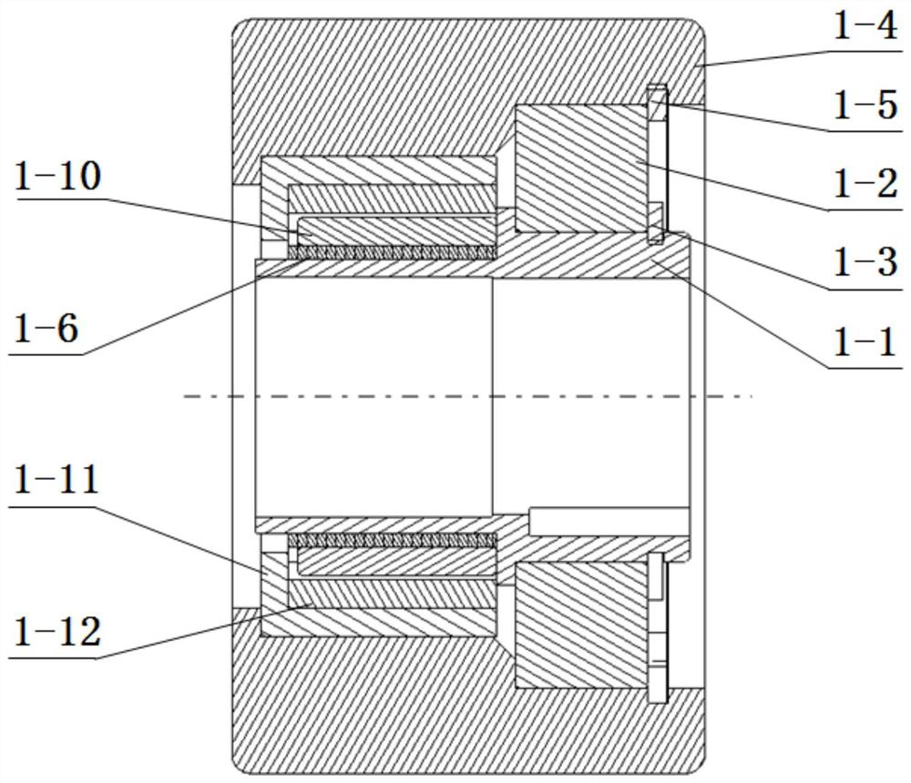
[0032] Such as figure 1 As shown, this embodiment provides a conveyor line roller with limited driving force, which is used to support the material pallet on the automatic roller conveyor line and drive it to move horizontally, which can limit the driving force without friction and wear, and contributes to Simplify the transmission mechanism of the roller conveyor line.

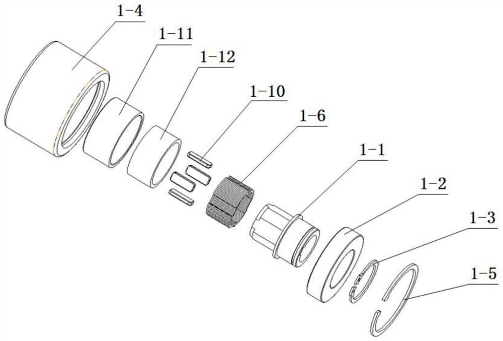
[0033] A roller for a transmission line that limits driving force, including a hollow shaft 1-1, a rolling bearing 1-2, an outer ring of the roller 1-4, an elastic retaining ring 1-5 for holes, a magnet bracket 1-6, and a spacer 1 -11 and iron core 1-12;

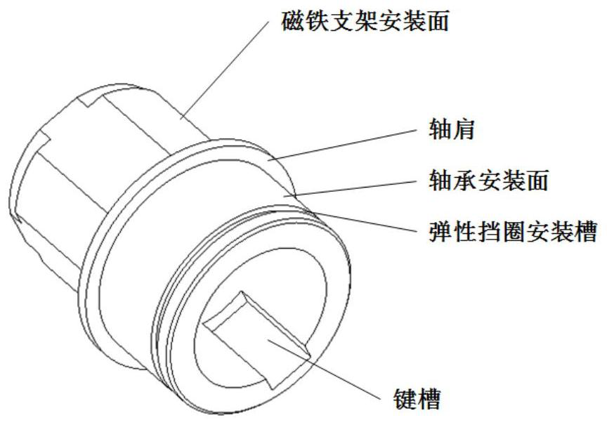
[0034] Such as image 3 and Figure 4 As shown, the hollow shaft 1-1 is introduced in detail. The inner hole of the hollow shaft 1-1 is slidingly fitted with the roller installation shaft. , the rolling bearing 1-2 is installed on the bearing installation surface, a circle of shaft shoulder and hollow shaft retaining ring installation groove are arrange...


PUM


Abstract

The invention discloses a conveying line roller capable of limiting driving force, and belongs to the technical field of automobiles. The conveying line roller capable of limiting driving force comprises a hollow shaft, a rolling bearing, a roller outer ring, a spacer bush and an iron core, wherein an inner hole of the hollow shaft is in sliding fit with a roller mounting shaft, one end of the hollow shaft is fixedly sleeved with the rolling bearing, an outer ring of the rolling bearing is tightly attached to an inner ring of the roller outer ring, the other end of the hollow shaft is fixedly sleeved with a magnet support, the magnet support is fixed, a magnet is installed on the magnet support, the outer ring of the magnet support is sleeved with the iron core, a certain gap is reserved between the inner ring of the iron core and the magnet, it is guaranteed that the iron core and the magnet can relatively rotate around the axis of the hollow shaft, the outer ring of the iron core is sleeved with the spacer bush, and the outer ring of the spacer bush is attached to the inner ring of the roller outer ring. According to the roller, a driving force limiting device is integrated on the roller, a moment limiting device is omitted, and the purpose of simplifying the mechanism is achieved; and the torque transmission process is in a non-contact mode, the problem that friction plates are abraded does not exist, and the maintenance work intensity and the use cost of the conveying line are reduced.

Description

technical field [0001] The invention belongs to the technical field of automobiles, and in particular relates to a roller for a conveying line that limits driving force. Background technique [0002] Roller conveyor lines are common equipment for automated assembly lines. In recent years, due to the promotion and use of new energy electric vehicles, the demand for electric vehicle battery packs and powertrain production lines has increased, and the use of roller conveyor lines has also increased. The roller conveyor line is driven by a motor, and the motor drives a long axis to rotate. The long axis is arranged along the conveyor line, and there are driving bevel gears on it every certain distance to drive the driven bevel gear meshing with it to rotate. The driven bevel gear drives the rollers coaxial with it, and a series of rollers drive the material pallets of the production line to be transported in a straight line through friction. Due to the continuous operation of t...

Claims


Application Information

Patent Timeline
Patent Type & Authority Applications(China)
IPC IPC(8): B65G39/02
CPCB65G39/02Y02P70/10
Inventor 张晓龙艾学崇宫正军董雷张锦枫杨立群林增宇
Owner CHINA FIRST AUTOMOBILE
Why Eureka
Try Eureka