Metal processing quenching liquid tank

A technology of metal processing and quenching tank, which is applied in the field of metal quenching, can solve the problems of affecting the quality of quenching, uneven temperature of quenching liquid, and inability to treat metal quenching, etc., and achieve the effects of improving heat absorption effect, enhancing quenching effect, and increasing pumping pressure

Pending Publication Date: 2021-12-31
徐州中顺尚奕机械制造有限公司
8 Cites 1 Cited by

AI-Extracted Technical Summary

Problems solved by technology

[0003] When quenching metal, the quenching liquid in the quenching liquid tank will absorb heat and heat up, so it is necessary to continuously cool the quenching liquid. In the prior art, the quenching liquid is circulated to cool. , it is easy to cause uneven temperature of t...

Method used

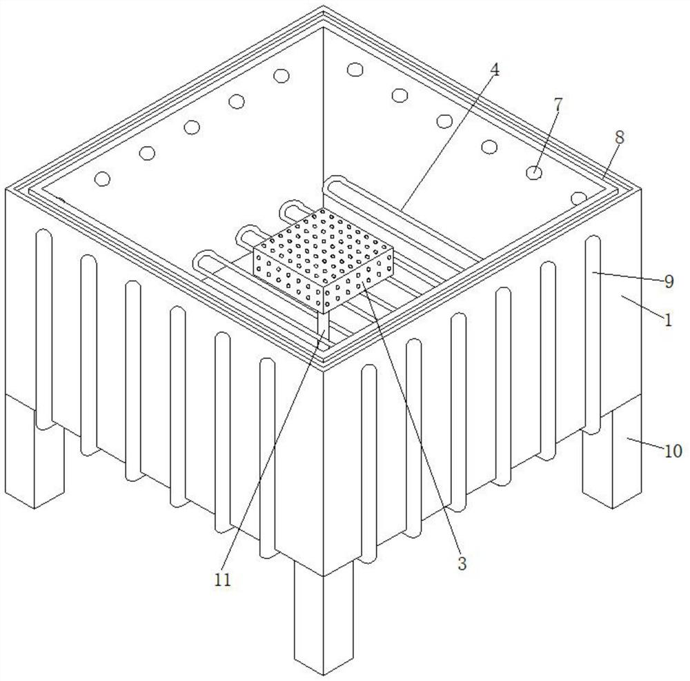
In an optional embodiment, the bottom four corners of the quenching tank 1 are all supported and fixed with legs 10, and four legs 10 are provided, in the present embodiment (please refer to Fig. 1 ) The supporting feet 10 at the four corners realize stable support to the quenching tank 1 .
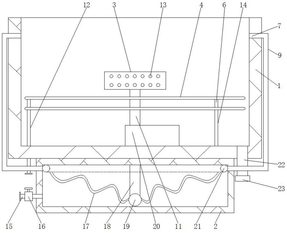
In an optional embodiment, the bottom of described quenching tank 1 is equipped with submersible booster pump 20, and the water inlet of submersible booster pump 20 is communicated with the bottom of suction pipe 11, and submersible booster pump 20 The water outlet of the water outlet is communicated with the top of the standpipe 18. In the present embodiment (please refer to Fig. 2) by making the bottom of the quenching tank 1 a submersible booster pump 20 is installed, the water inlet of the submersible booster pump 20 is connected with the suction pipe 11 The bottom is connected, and the water outlet of the submersible booster pump 20 is connected with the top of the vertical pipe 18. When in use, the pumping pressure to the quenching liquid can be increased by the submersible booster pump 20 to ensure rapid cooling of the quenching liquid.
In an optional embodiment, the first copper tube 4 is distributed in the inside of the quenching tank 1 in an S shape, and the first copper tube 4 above and the first copper tube 4 below are parallel to each other. In the embodiment (please refer to FIG. 1 and FIG. 2 ), the contact area between the first copper tube 4 and the quench...

Abstract

The invention relates to the technical field of metal quenching, and discloses a metal processing quenching liquid tank. The metal processing quenching liquid tank comprises a quenching tank, a water box, a liquid absorption frame, first copper pipes and a filter screen; and the water box is fixed to the bottom of the quenching tank and fixed to the middle position of the bottom of the quenching tank, a water adding pipe is connected to the lower portion of the left side of the water box and communicates with the interior of the water box, a vertical pipe is vertically arranged below the middle of the water box, the bottom of the vertical pipe is connected with a hollow ball, and the hollow ball communicates with the interior of the vertical pipe. Quenching liquid which is just heated is absorbed into second copper pipes in the water box through the liquid absorption frame arranged on the upper portion in the quenching liquid, after being rapidly cooled, the quenching liquid is uniformly discharged into the quenching tank from the periphery, the low-temperature and uniform-temperature state of the quenching liquid above is ensured, the first copper pipes connected with circulating water in cooperation and arranged in the quenching tank are adopted for cooperation, the direct cooling effect on the quenching liquid in the quenching tank can be increased, the low-temperature state of the quenching liquid is kept, and the quenching effect on metal is improved.

Application Domain

Quenching devices

Technology Topic

Water pipeWater tanks +7

Image

  • Metal processing quenching liquid tank
  • Metal processing quenching liquid tank
  • Metal processing quenching liquid tank

Examples

  • Experimental program(1)

Example Embodiment

[0028] In order to make the technical means, creative features, goals and effects achieved by the present invention easy to understand, the present invention will be further described below in conjunction with specific embodiments.
[0029] In describing the present invention, it should be understood that the terms "upper", "lower", "front", "rear", "left", "right", "top", "bottom", "inner", " The orientation or positional relationship indicated by "outside", etc. is based on the orientation or positional relationship shown in the drawings, and is only for the convenience of describing the present invention and simplifying the description, rather than indicating or implying that the referred device or element must have a specific orientation, so as to Specific orientation configurations and operations, therefore, are not to be construed as limitations on the invention.
[0030] In the description of the present invention, it should be noted that, unless otherwise specified and limited, the terms "installation", "connection", and "setting" should be understood in a broad sense, for example, it can be fixed connection, setting, or Detachable connection and setting, or integral connection and setting; the models of the electrical appliances provided in the present invention are for reference only. Those of ordinary skill in the art can replace different types of electrical appliances with the same function according to actual usage conditions, and those of ordinary skill in the art can understand the specific meanings of the above terms in the present invention in specific situations.
[0031] see Figure 1-4 , the present invention provides a technical solution: a quenching liquid tank for metal processing, including a quenching tank 1, a water tank 2, a liquid suction frame 3, a first copper tube 4 and a filter screen 5; the water tank 2 is fixed on the side of the quenching tank 1 bottom, and the water tank 2 is fixed in the middle of the bottom of the quenching tank 1;
[0032] The lower left side of the water tank 2 is connected with a water adding pipe 15, and the water adding pipe 15 communicates with the inside of the water tank 2. A vertical pipe 18 is vertically arranged below the middle part of the water tank 2. The bottom of the vertical pipe 18 is connected with a hollow ball 19, and the hollow The ball 19 communicates with the inside of the standpipe 18, and a ring pipe 21 is fixed around the inner upper outer ring of the water tank 2, and the ring pipe 21 is fixed on the upper inner wall of the water tank 2 around, and a second copper tube is connected between the hollow ball 19 and the ring pipe 21. tube 17, and the two ends of the second copper tube 17 communicate with the ring tube 21 and the hollow ball 19 respectively, and there are multiple second copper tubes 17, and the upper outer ring surface of the quenching tank 1 is provided with through holes 7. The through holes 7 are evenly distributed in the inner circle of the quenching tank 1. The surface of the quenching tank 1 outside the through holes 7 is connected with a return pipe 9. The return pipe 9 communicates with the inside of the through hole 7, and the bottom of the return pipe 9 penetrates to the water tank. 2, the bottom of the return pipe 9 communicates with the annular pipe 21 inside the water tank 2;
[0033] The liquid suction frame 3 is located above the middle part of the inner side of the quenching tank 1, and the lower middle part of the liquid suction frame 3 is vertically connected with a liquid suction pipe 11, and the liquid suction pipe 11 communicates with the inside of the liquid suction frame 3, and the liquid suction pipe 11 The bottom of the bottom of the water tank 2 communicates with the vertical pipe 18 inside the water tank 2. The surface of the liquid suction frame 3 is provided with a liquid suction hole 13. There are a plurality of liquid suction holes 13, and the plurality of liquid suction holes 13 are evenly distributed on the surface of the liquid suction frame 3. surface;
[0034] The first copper tube 4 is horizontally arranged inside the quenching tank 1, and there are two first copper tubes 4, and the two first copper tubes 4 are located inside the quenching tank 1 below the liquid suction frame 3, and the first copper tube above Both sides of the copper pipe 4 and the lower first copper pipe 4 are connected through the connecting pipe 6, and the lower right side of the lower first copper pipe 4 is vertically connected with a water inlet pipe 14, and the bottom of the water inlet pipe 14 penetrates to the water tank 2 The interior communicates with the inside of the water tank 2, and the lower left side of the first copper pipe 4 is vertically connected with an outlet pipe 12, and the lower part of the outlet pipe 12 penetrates to the outside of the quenching tank 1;
[0035] The upper surface of the filter screen 5 is surrounded by a ring plate 24, the ring plate 24 is fixed on the upper surface of the filter screen 5 by welding, and the upper outer ring surface of the ring plate 24 is fixed with a handle 25, and the handle 25 is provided with multiple One, and the handle 25 is fixed on the upper surface of the ring plate 24 by welding, the outer surface of the lower ring plate 24 is surrounded by an annular block 26, the right side of the quenching tank 1 is connected with a drain pipe 22, and the drain pipe 22 communicates with the inside of the quenching tank 1 , and a sealing cover 23 is screwed and fixed on the drain pipe 22 .
[0036] In the present invention, when in use, the water supply pipe 15 is first connected to the cold water supply pipe, the water outlet pipe 12 is connected to the return pipe, and then the quenching liquid is added to the quenching tank 1 until the quenching liquid diffuses to the top of the quenching tank 1, and then Open the valve 16 on the water supply pipe 15, so that cold water enters the water tank 2 and fills the inside of the water tank 2, then enters the inside of the first copper pipe 4 along the water inlet pipe 14, and flows to the left inside the first copper pipe 4. It is discharged from the outlet pipe 12 to complete the circling of the cold water, and at the same time, the quenching liquid inside the quenching tank 1 is pumped from the liquid pumping hole 13 into the liquid pumping pipe 11, and then enters the vertical pipe 18 and the hollow ball 19. The second copper pipe 17 then enters the ring pipe 21, and finally enters the quenching tank 1 through the return pipe 9 through the through hole 7 to complete the circulation of the quenching liquid. When quenching, the metal heated to a certain temperature is hoisted to the quenching tank The upper part of 1 is quenched by the action of the quenching liquid, and the heated quenching liquid can directly enter the liquid suction frame 3 from the liquid pumping hole 13 below, and finally enter the second copper pipe 17, and the circulating cold water inside the water tank 2 function, so that the heat is absorbed, and then enters from the top to the top of the quenching tank 1 through the return pipe 9, keeps the low temperature of the quenching liquid above, and discharges it from all sides to ensure the uniformity of temperature. The cold water flowing inside the pipe 4 can also directly absorb the temperature of the quenching liquid inside the quenching tank 1, maintain the temperature inside the quenching tank 1, increase the distribution of the temperature of the quenching liquid, and when waste chips may be generated during the quenching process, the filter screen 5 can be used Under the action of the ring plate 24 supporting above the quenching tank 1, the filter screen 5 is placed above the liquid suction frame 3 inside the quenching tank 1, and the waste chips generated in the quenching process can be filtered out, and then the filter screen 5 can be taken out to clean up the waste. Chips, close the valve 16 on the water supply pipe 15 after quenching is all over, unscrew the sealing cover 23 at the bottom of the drain pipe 22, the quenching liquid in the quenching tank 1 can be discharged and collected or processed.
[0037] In an optional embodiment, the upper surface of the quenching tank 1 is provided with an annular groove 8, and the annular groove 8 is arranged on the upper outer ring of the quenching tank 1, in this embodiment (please refer to figure 1 ) By making the upper surface of the quenching tank 1 be provided with a ring groove 8, and the ring groove 8 is surrounded by being arranged on the upper outer ring of the quenching tank 1, when the filter screen 5 needs to be placed on the inside of the quenching tank 1 through the ring plate 24, The ring block 26 at the bottom of the ring plate 24 is supported inside the ring groove 8 and has a stabilizing effect on the support of the ring plate 24 .
[0038] In an optional embodiment, a submersible booster pump 20 is installed at the bottom of the quenching tank 1, the water inlet of the submersible booster pump 20 communicates with the bottom of the suction pipe 11, and the water outlet of the submersible booster pump 20 Communicate with the top of the vertical pipe 18, in the present embodiment (see figure 2 ) by making the bottom of the quenching tank 1 equipped with a submersible booster pump 20, the water inlet of the submersible booster pump 20 communicates with the bottom of the pumping pipe 11, and the water outlet of the submersible booster pump 20 communicates with the top of the vertical pipe 18, When in use, the submersible booster pump 20 can be used to increase the pumping pressure of the quenching liquid to ensure rapid cooling of the quenching liquid.
[0039] In an optional embodiment, the second copper pipe 17 is spirally distributed inside the water tank 2, and the second copper pipe 17 is obliquely connected between the hollow ball 19 and the ring pipe 21. In this embodiment in (see figure 2 ) By making the second copper tube 17 spirally distributed inside the water tank 2, and the second copper tube 17 is obliquely connected between the hollow ball 19 and the ring tube 21, the second copper tube 17 that is spirally arranged can increase the The contact area between the second copper tube 17 and the water inside the water tank 2 improves the heat absorption effect on the quenching liquid inside the second copper tube 17 .
[0040] In an optional embodiment, four corners of the bottom of the quenching tank 1 are supported and fixed with legs 10, and there are four legs 10, in this embodiment (please refer to figure 1 ) to achieve stable support for the quenching tank 1 through the legs 10 at the four corners below the quenching tank 1 .
[0041] In an optional embodiment, the first copper tubes 4 are distributed in the quenching tank 1 in an S shape, and the upper first copper tubes 4 and the lower first copper tubes 4 are parallel to each other. In this embodiment (see figure 1 and figure 2 ) Through the S-shaped distribution of the first copper tube 4, the contact area between the first copper tube 4 and the quenching liquid inside the quenching tank 1 is increased.
[0042] In an optional embodiment, a valve 16 is installed on the water adding pipe 15, and the valve 16 communicates with the inside of the water adding pipe 15. In this embodiment (see figure 2 ) can control the opening and closing state of the water adding pipe 15 through the valve 16.
[0043] In an optional embodiment, the submersible booster pump 20 is electrically connected to an external control device through wires. In this embodiment (see figure 2 ) control the opening and closing of the submersible booster pump 20 through an external control device.
[0044] It should be noted that the present invention is a metal processing quenching liquid tank, including a quenching tank 1, a water tank 2, a liquid suction frame 3, a first copper pipe 4, a filter screen 5, a connecting pipe 6, a through hole 7, and a ring groove 8 , return pipe 9, legs 10, pumping pipe 11, outlet pipe 12, pumping hole 13, water inlet pipe 14, water pipe 15, valve 16, second copper pipe 17, standpipe 18, hollow ball 19, submersible pressurization Pump 20, ring pipe 21, drain pipe 22, seal cover 23, ring plate 24, handle 25, ring clamping block 26, the components are all general standard parts or components known to those skilled in the art, and their structures and principles are all in the field. Technicians can know from the technical manual or through conventional experimental methods that all the above-mentioned electrical components, which refer to power components, electrical components, and the adapted monitoring computer and power supply, are connected through wires in the idle space of the device. The connection method should refer to the above working principle, and the electrical connection between the electrical devices is completed in sequence. The detailed connection method is a well-known technology in the field. The above mainly introduces the working principle and process, and does not explain the electrical control.

PUM

no PUM

Description & Claims & Application Information

We can also present the details of the Description, Claims and Application information to help users get a comprehensive understanding of the technical details of the patent, such as background art, summary of invention, brief description of drawings, description of embodiments, and other original content. On the other hand, users can also determine the specific scope of protection of the technology through the list of claims; as well as understand the changes in the life cycle of the technology with the presentation of the patent timeline. Login to view more.

Similar technology patents

A Quenching Device for Large Forged Fan Spindle

ActiveCN110106340Bspeed up coolingImprove quenching effect
Owner:SHANDONG LAIWU JINLEI WIND POWER TECH

Safe portable multifunctional oxygen-hydrogen integrated machine

ActiveCN105063652Aincrease contact areaIncreased solubility
Owner:保定市氢水源生物科技有限公司

Touch panel

ActiveUS20140184936A1reduce visibilityincrease contact area
Owner:SAMSUNG ELECTRO MECHANICS CO LTD

Classification and recommendation of technical efficacy words

  • Improve quenching effect

A Quenching Device for Large Forged Fan Spindle

ActiveCN110106340Bspeed up coolingImprove quenching effect
Owner:SHANDONG LAIWU JINLEI WIND POWER TECH
Why Eureka
Try Eureka