
Relay anti-arcing circuit and control method

A control method and relay technology, applied in the direction of relays, circuits, electrical components, etc., can solve the problems of easy-to-burn contact springs, etc., and achieve the effect of improving reliability and simple circuit structure

Pending Publication Date: 2021-12-31
SHENZHEN YINGFEIYUAN TECH CO LTD
View PDF0 Cites 0 Cited by
  • Summary
  • Abstract
  • Description
  • Claims
  • Application Information

AI Technical Summary

Problems solved by technology

[0004] The technical problem to be solved by the present invention is to provide a relay anti-arc circuit and control method, which aims to solve the problem that the energy generated by the arc is easy to burn the contact spring when the contact is disconnected in the traditional relay

Method used


Image

  • Relay anti-arcing circuit and control method
  • Relay anti-arcing circuit and control method
  • Relay anti-arcing circuit and control method

Examples


Embodiment 1

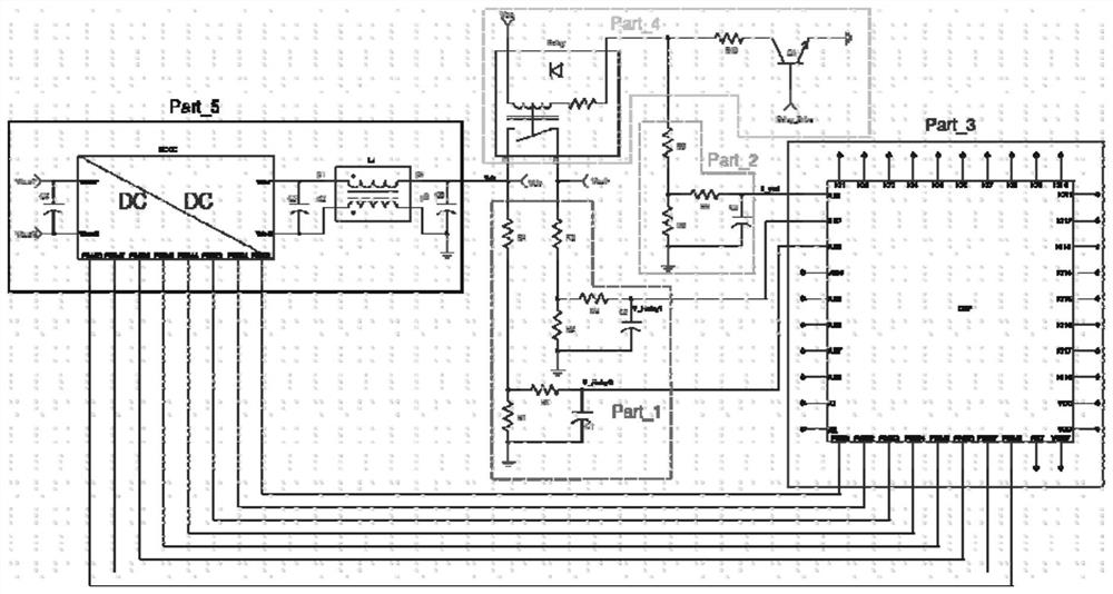
[0037] Such as figure 1 As shown, the first aspect of the present invention provides a relay anti-arc circuit, including a relay and its drive circuit, and also includes a voltage detection circuit, a central controller and a main power drive circuit; wherein,

[0038] The voltage detection circuit is used to detect the voltage signal of the relay and send the voltage signal to the central controller;

[0039] The central controller is used for logical analysis and control of voltage signals, and outputs control signals according to the logical analysis results;

[0040] The main power drive circuit is used to close or maintain the current input to the relay according to the control signal.

[0041] exist figure 1 As shown, the relay and its drive circuit are divided into one part, and the voltage detection circuit includes two groups, therefore, figure 1 The shown relay anti-arc circuit divides the circuit composition of this application into 5 parts, namely the relay and ...

Embodiment 2

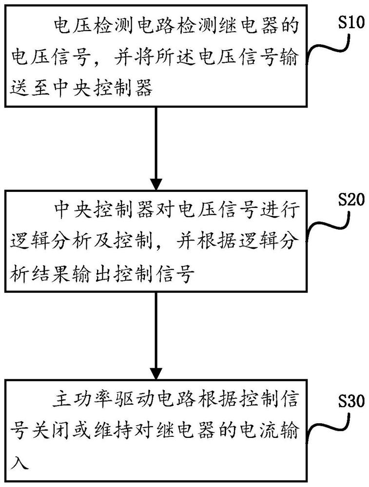
[0053] The second aspect of the present invention provides a control method, which is applied to the above-mentioned relay anti-arc circuit. The relay anti-arc circuit includes a relay, a relay drive circuit connected to the relay, a voltage detection circuit, a central controller and a main power drive circuit. , the specific circuit structure can refer to the description in Embodiment 1, and will not be repeated here, wherein, the control method is as follows figure 2 shown, including:

[0054] Step S10, the voltage detection circuit detects the voltage signal of the relay, and sends the voltage signal to the central controller.

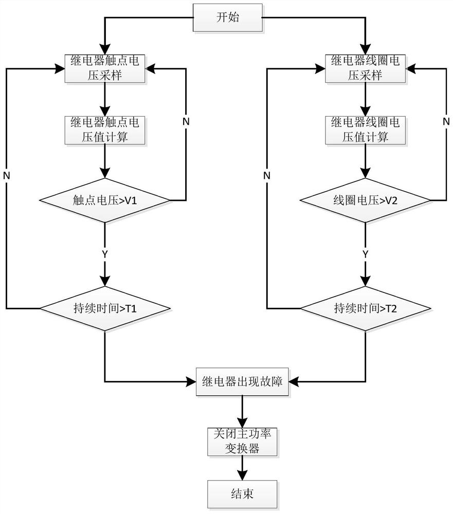
[0055] The detection of the voltage signal can adopt the detection method of the above-mentioned resistance voltage division, its circuit topology has been specifically described in embodiment 1, or other detection methods such as an operational amplifier circuit or an external hardware comparison circuit are used, and the basis of determining the...


PUM


Abstract

The invention provides a relay anti-arcing circuit and a control method, the relay anti-arcing circuit comprises a relay and a relay driving circuit connected with the relay, and also comprises a voltage detection circuit, a central controller and a main power driving circuit. The voltage detection circuit, the central controller and the main power driving circuit are sequentially connected, and the control method comprises the following steps: the voltage detection circuit detects a voltage signal in the relay and sends the voltage signal to the central controller, and the central processor performs logic analysis and judgment according to the received voltage signal; when an abnormal fault occurs, the main power driving circuit is controlled to close main power transmission in time, so that the relay is separated from a contact reed under the condition of zero current or small current, power conversion under normal conditions and rapid protection under abnormal conditions are realized, the reliability of the whole circuit is improved, and the service life of the relay is prolonged. The detection control scheme provided by the invention is small in occupied space, low in cost and capable of well realizing relay contact disconnection.

Description

technical field [0001] The invention belongs to the technical field of relays, and in particular relates to a relay anti-arc circuit and a control method. Background technique [0002] With the rapid development of smart grid and energy interconnection, products that convert and transmit electric energy in two directions have gradually become market hotspots in this field. [0003] The power relay is one of the key components of the bidirectional converter, and the reliability of the relay is an important guarantee for the reliability of the converter. Due to the power relay, when the contacts are disconnected under abnormal conditions, an arc will be drawn between the contact reeds, and the energy of the arc will often burn the contact reeds, or even the entire relay. Therefore, there is a need for a solution to the problem of relay arcing, so as to ensure that the relay can be reliably disconnected under abnormal conditions, thereby improving the reliability of the entire...

Claims


Application Information

Patent Timeline
IPC IPC(8): H01H47/02H01H47/00
CPCH01H47/02H01H47/002
Inventor 吕华军余泽汇聂少波
Owner SHENZHEN YINGFEIYUAN TECH CO LTD
Learn More