Wire harness structure of vehicle distribution box
A technology for distribution boxes and wiring harnesses, applied in circuits, electrical components, vehicle components, etc., can solve the problems of repeated design, waste of manpower and material resources, and achieve the effect of avoiding connection errors, saving space, and simplifying the production process.
- Summary
- Abstract
- Description
- Claims
- Application Information
AI Technical Summary
Problems solved by technology
Method used
Image
Examples
Embodiment 1
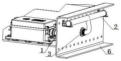
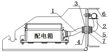
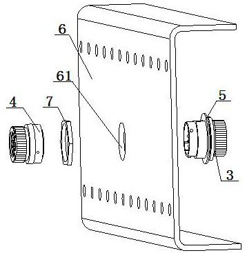
[0040] A wiring harness structure for a vehicle distribution box, the distribution box wiring harness includes: a distribution box terminal wiring harness 1 and an electrical appliance terminal wiring harness 2, and the distribution box terminal wiring harness 1 is connected to the electrical appliance terminal wiring harness 2 through a connector 3 connection; the connector 3 includes a female connection terminal 4 and a male connection terminal 5, one end of the female connection terminal 4 is connected to the distribution box end wire harness 1, and the other end of the female connection terminal 4 is set There is a terminal plug 41, and the terminal plug 41 is provided with a plurality of terminal jacks 45; one end of the public connection terminal 5 is connected to the electrical appliance terminal harness 2, and the other end of the public connection terminal 5 is provided with A terminal needle holder 51 is provided, and a plurality of terminal needles 54 are arranged in...
Embodiment 2
[0042] Embodiment 2 is basically the same as Embodiment 1, and its difference is:
[0043] One end of the wiring harness 1 at the end of the distribution box is connected to the distribution box, the other end of the wiring harness 1 at the end of the distribution box is connected to one end of the connector 3, and the other end of the connector 3 is connected to the wiring harness at the end of the electrical appliance. 2 phase connection, the other end of the electrical appliance end wire harness 2 is connected to the terminal of each electrical appliance; the outer circumference of the terminal plug 41 is provided with a main rail 46, and the main rail 46 is parallel to the terminal plug 41. The central axis is set; the inner peripheral surface of the fixed snap ring 52 is provided with a main chute 55, the main rail 46 is correspondingly arranged with the main chute 55, and the main rail 46 is slidably matched with the main chute 55; A plurality of auxiliary rails 47 are a...
Embodiment 3
[0045] Embodiment 3 is basically the same as Embodiment 2, and its difference is:
[0046] The connector 3 is fixed on the middle part of the vehicle frame longitudinal beam 6, and the electrical appliance terminal harness 2 is fixed on the inner side of the vehicle frame longitudinal beam 6; the outer peripheral wall of the terminal needle seat 51 is provided with external threads, and the terminal An alignment platform 57 is provided on the needle seat 51, and a position-limiting structure with the alignment platform 57 is provided on the fixing hole 61 in the middle of the vehicle frame longitudinal beam 6, and the terminal needle seat 51 is connected to the fixing screw after passing through the fixing hole 61. Cap 7 threaded connection.
PUM
 Abstract
Description
Claims
Application Information
 - R&D
- Intellectual Property
- Life Sciences
- Materials
- Tech Scout
- Unparalleled Data Quality
- Higher Quality Content
- 60% Fewer Hallucinations
Browse by: Latest US Patents, China's latest patents, Technical Efficacy Thesaurus, Application Domain, Technology Topic, Popular Technical Reports.
© 2025 PatSnap. All rights reserved.Legal|Privacy policy|Modern Slavery Act Transparency Statement|Sitemap|About US| Contact US: help@patsnap.com


