
Force application device for a control stick

A kind of equipment and lever technology, applied in the field of driving equipment, can solve the problems of expensive system, reduced dynamic performance of the steering column, and bulkiness

Pending Publication Date: 2021-12-31
SAFRAN ELECTRONICS & DEFENSE
View PDF12 Cites 0 Cited by
  • Summary
  • Abstract
  • Description
  • Claims
  • Application Information

AI Technical Summary

Problems solved by technology

These systems can be expensive, bulky and difficult to integrate into aircraft cockpits
In addition, the introduction of gears means that the dynamic performance of the control column is reduced, the inertia of the control column is increased, and there is a loss of ergonomics, because the pilot feels the torque changes due to the presence of the gears
[0011] The prior art does not provide a suitable solution with limited space requirements and good durability for maintaining force feedback at the lever in case of failure of the force feedback motor

Method used


Image

  • Force application device for a control stick
  • Force application device for a control stick
  • Force application device for a control stick

Examples


Embodiment Construction

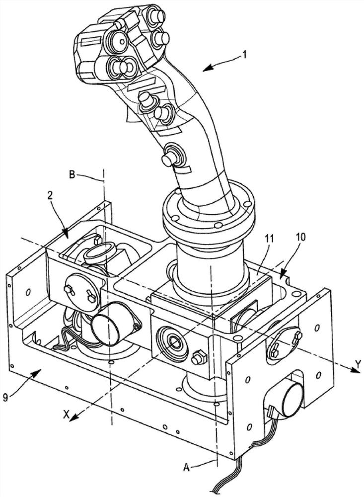
[0067] An example will be described next in relation to an aircraft control stick that can be moved rotationally along a roll axis as well as along a pitch axis. However, the inventive force application device has the same advantages when used in combination with a steering column which is movable along one or more axes of movement different from the axis of rotation of the roll or the axis of rotation of the pitch.

[0068] In the following, the "law of damping" of a magnetic brake expresses the relationship between the rotational position of the lever along the axis of rotation and the resistance produced by the brake against rotational movement about said axis. Furthermore, the "law of force" expresses the relationship between the position of the lever and the total force returned to the lever, which may be resistive or dynamic (the total force takes into account the force of one or more mechanical brakes action, possibly also taking into account the action of one or more f...


PUM


Abstract

The present invention relates to a force application device for a control stick of an aircraft, wherein the control stick comprises a control lever (1) rotating a shaft (A1) about a first axis (A), the device comprising a magnetic brake (5a) which comprises a magnetisable element (50a) mounted on the shaft and a magnetic transmitter (51a) which is opposite the magnetisable element and free to rotate about the first axis relative to the magnetisable element, the magnetic transmitter having an activated state in which the magnetic transmitter is supplied with current and generates a magnetic field in a volume occupied by the magnetisable element, and a deactivated state in which the magnetic transmitter is not supplied with current and does not generate a magnetic field, so as to prevent the magnetisable element from rotating about the shaft relative to the magnetic transmitter.

Description

technical field [0001] The invention relates to piloting equipment used by pilots in aircraft cockpits. The invention particularly relates to active control sticks that include integrated force feedback to assist the pilot. Background technique [0002] Piloting equipment in the cockpit of an aircraft usually comprises a control stick, in particular, which has a control lever mounted in rotation about an axis known as the roll axis and an axis known as the pitch axis, both The axes are orthogonal to each other. Devices of the "joystick" type are the most commonly encountered. [0003] Depending on the position of the levers along these two axes, the steering device sends movement commands to the steering components of the aircraft. [0004] On the latest aircraft models, the movement commands of the aircraft are electronic, and the piloting equipment integrated into the cockpit can be of the "sidestick" type. The position of the lever along the roll and pitch axes is mea...

Claims


Application Information

Patent Timeline
Patent Type & Authority Applications(China)
IPC IPC(8): B64C13/04G05G9/047G06F3/01B64C13/50
CPCB64C13/0421B64C13/503B64C13/507G05G9/047G06F3/016G05G2009/04774G05G2009/04718G05G2009/04766G05G2009/04748
Inventor R-L·罗尼扎克扬尼克·阿特拉齐克
Owner SAFRAN ELECTRONICS & DEFENSE
Learn More